1
- 11
2WAY SYSTEM
Control Functions-Outdoor Unit
1
4. Output of PCB
Indication on PCB
Remarks
Item
4-way valve
Electromagnetic valve
Save valve
Refrigerant control valve
Refrigerant balance valve
Oil recoverly valve
By-pass valve
Refrigerant interception valve
Motor operated valve
MOV for heat exchanger 1
MOV for heat exchanger 2
SC Circuit Electronic control valve
Crankcase heater
Crankcase heater for inverter
Crankcase heater for constant speed 1
Crankcase heater for constant speed 2
20S
SAVE
RCV
RBV
ORVR
BPV
O2
MOV1
MOV2
MOV4
CH1
CH2
CH3
4-1. 4-way valve [20S]
- This valve turns OFF at cooling, and turns ON at heating operation.
- This valve turns OFF at defrosting.
* When the outdoor unit stops, the 4-way valve maintains the same state just before. However, when the system
stopped condition continues for 30 minutes, it is turned OFF.
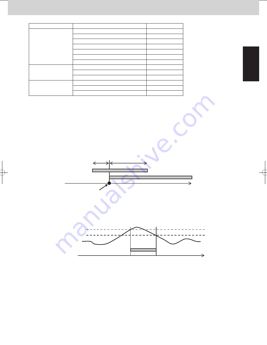
4-2. SAVE valve [SAVE]
- This valve turns ON for 5 seconds before the inverter compressor starts. After the inverter compressor starts, the
valve turns ON for 10 seconds. After that, it turns OFF.
- This valve turns ON for 30 seconds after the outdoor unit stops. After that, it turns OFF.
- This valve turns ON when high pressure sensor detects 3.4MPa to prevent abnormal pressure. This valve turns
OFF when the high pressure goes down below 3.3MPa.
Inverter compressor start
SAVE valve
5 seconds
10 seconds
Inverter compressor
- This valve might turn ON when the system capacity is excessive although the inverter compressor operates at
- This valve turns ON in the following status :
Min. frequency.
(Compressor discharge temperature - High pressure saturation temperature) < 5°C
SAVE valve
3.3MPa
3.4MPa
High pressure
1
- 10
1
3-7-4. Primary current protection of HIC board
The fan motor current is included in primary current. PCB is protected from the power consumption increase of
fan motor when the heat exchanger is blocked by frost, etc.
Limit current 1
Max. current 1L
Stop
If this current is detected at regular intervals, alarm appears.
Frequency of inverter compressor goes down.
Frequency of inverter compressor can increase.
Frequency of inverter comp
ressor cannot increase.
Max. current 1H
Reference
Inverter layout
Diode Bridge
Power Source
IPM(FN)
Magnet SW
Noise Filter
L3
L1
L2
Noise Filter
IPM(CM)
Fan Motor
Compressor
W
U
V
W
U
V
Primary CT
Secondary CT
*When restarting after stopping by protection control, the compressor capacity will increase slowly.
2WAY SYSTEM
Control Functions-Outdoor Unit
3. Compressor Control
Limit current 1
Primary
current
Max. current 1 H
unit : Amp.
10HP
19.8
16.8
15.8
8HP
15.1
12.1
11.1
12HP
18.0
15.0
14.0
14HP
21.0
18.0
17.0
16HP
21.0
18.0
17.0
18HP
21.0
18.0
17.0
20HP
21.0
18.0
17.0
Max. current 1 L
SM830204-05_2WAY SYS.indb 11
2015/01/21 17:00:00
Summary of Contents for U-20ME1E81
Page 54: ... MEMO 1 46 ...
Page 102: ... MEMO 3 36 ...
Page 116: ... MEMO 4 14 ...
Page 177: ...201502 ...


