Service Checker
1. Outdoor Unit Maintenance Remote Controller
1
2
3
4
5
6
7
8
6
- 7
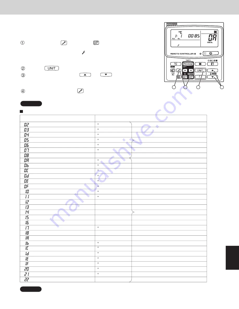
1-4. Monitoring Operations
Display the indoor unit and outdoor unit sensor temperatures.
<Operating procedure>
Press and hold the
(CHECK) and
(CANCEL) buttons simultaneously
for 4 seconds or longer to engage temperature monitor mode.
During temperature monitoring,
displays.
(The display and operations are the same as for monitor mode using the
indoor unit remote controller.)
Press the
(UNIT) button and select the indoor unit to monitor.
Press the temperature setting
and
buttons and select the
item code of the temperature to monitor. The unit No. of the selected indoor
unit, and the temperature data, are displayed.
To end monitoring, press the
(CHECK) button.
The display returns to the normal display.
NOTE
The display does not blink.
1
2
4
3
0A and subsequent items are outdoor unit data. 0A – 22 are for unit No. 1.
2A – 42 are for unit No. 2.
NOTE
Display of unit No. 1 (main unit)
Not used
DN
Description
Remarks
Indoor unit electronic control valve position
STEP
Intake temp.
F
Inverter primary current
A
Current at Compressor 2 (CT2)
A
MOV1 pulse
STEP
MOV2 pulse
STEP
Current at Compressor 3 (CT3)
A
MOV3 pulse
STEP
Actual operating frequency
Hz
E1
F
E2
F
E3
F
Discharge temp.
F
Discharge temp. setting
F
Discharge temp. 1 at Compressor 1
F
Heat exchanger gas 3
F
Heat exchanger liquid 3
F
Low-pressure sensor temp.
F
Suction temp.
F
Oil 1
F
Oil 2
F
Oil 3
F
Discharge temp. 2 at Compressor 2
F
High-pressure sensor temp.
F
Heat exchanger gas 1
F
Heat exchanger liquid 1
F
Heat exchanger gas 2
F
Heat exchanger liquid 2
F
Outdoor air temp.
F
Discharge temp. 3 at Compressor 3
F
Outdoor unit
Indoor unit
SM830202-00̲3WAY VRF.indb 7
SM830202-00̲3WAY VRF.indb 7
2012/01/30 14:53:47
2012/01/30 14:53:47
Summary of Contents for U-72MF1U9
Page 90: ...3 28 MEMO 1 2 3 4 5 6 7 ...
Page 112: ...4 22 1 2 3 4 5 6 7 MEMO ...
Page 127: ... MEMO 1 2 3 4 5 6 7 6 11 ...
Page 128: ...201201 ...


