


Design of 3WAY VRF SYSTEM
2
- 17
1
2
3
4
5
6
7
8
1. Model Selecting and Capacity Calculator
If the maximum tubing length (L1) exceeds 295 ft (equivalent length), increase the tubing size of the main liquid, gas tubes(LM)
by one rank.
However, the upper limit for the gas tube size is
ø
1-3/8".
Increasing the tubing size of the gas tubes can reduce the loss of capacity caused by longer tubing lengths.
Refer to Table 2-11 to increase the tubing size. However, the maximum allowable tubing length must not be exceeded.
*
The amount of additional refrigerant charge is determined from the liquid tube size only.
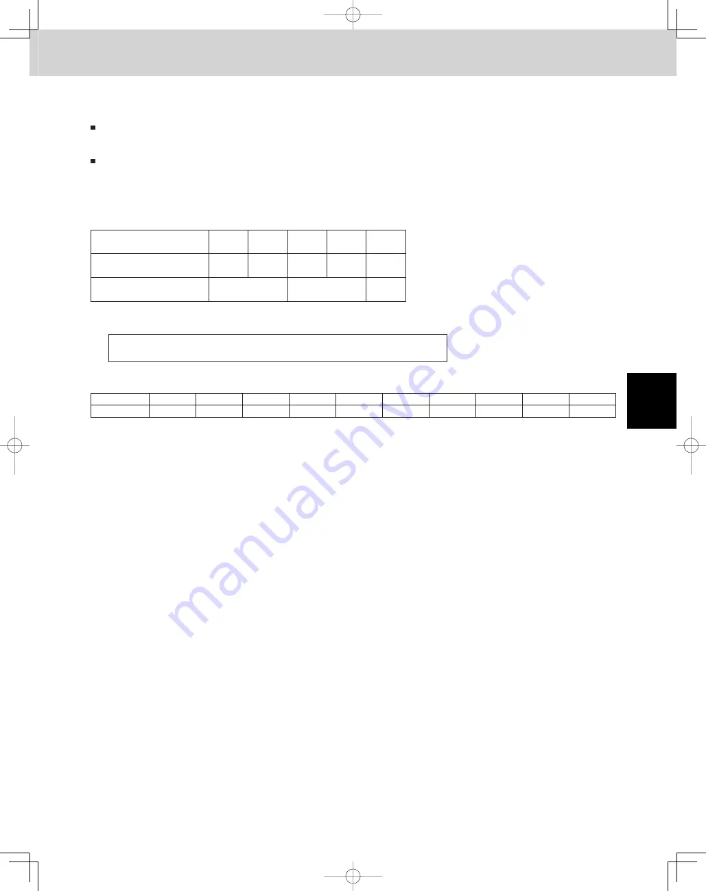
Table 2-10 Correction coefficient for equivalent length when the size of the gas tube (LM) is increased
Standard tube diameter
(gas tube, in.(mm))
ø1/2"
(ø12.7)
ø5/8"
(ø15.88)
ø3/4"
(ø19.05)
ø7/8"
(ø22.22)
ø1-1/8"
(ø28.58)
Tube diameter after change
(gas tube, in.(mm))
ø5/8"
(ø15.88)
ø3/4"
(ø19.05)
ø7/8"
(ø22.22)
ø1-1/8"
(ø28.58)
ø1-3/8"
(ø34.92)
Equivalent length correction
coefficient
0.4
0.5
0.6
*
When increasing the size of the suction and discharge tubing (LM), multiply by the
correction coefficient from Table 2-11 and calculate the equivalent length for section LM.
Tubing equivalent length after size increase
= Standard tubing equivalent length × Equivalent length correction coefficient
Table 2-11 Dimensions for connections of each part
Unit: in.
Position
A
B
C
D
E
F
G
H
I
J
Dimension
ø1-1/2"
ø1-1/4"
ø1-1/8"
ø1"
ø7/8"
ø3/4"
ø5/8"
ø1/2"
ø3/8"
−
TD831158-00̲3WAY̲VRF̲SYS.indb 17
TD831158-00̲3WAY̲VRF̲SYS.indb 17
2012/01/23 17:30:14
2012/01/23 17:30:14
Summary of Contents for U-72MF1U9
Page 118: ...Section 8 TENTATIVE ...


