


Design of 3WAY VRF SYSTEM
2
- 20
8
7
6
5
4
3
2
1
2. System Design
(3) Increasing the size of the refrigerant tubing
Increasing the tubing size of the gas tubes can reduce the loss of capacity caused by longer tubing lengths.
Refer to Table 2-11 to increase the tubing size. However, the maximum allowable tubing length must not be exceeded.
*
The amount of additional refrigerant charge is determined from the liquid tube size only.
Table 2-10 Correction coeffi cient for equivalent length when the size of the gas tube (LM) is increased
Standard tube diameter
(gas tube, in.(mm))
ø1/2"
(ø12.7)
ø5/8"
(ø15.88)
ø3/4"
(ø19.05)
ø7/8"
(ø22.22)
ø1-1/8"
(ø28.58)
Tube diameter after change
(gas tube, in.(mm))
ø5/8"
(ø15.88)
ø3/4"
(ø19.05)
ø7/8"
(ø22.22)
ø1-1/8"
(ø28.58)
ø1-3/8"
(ø34.92)
Equivalent length correction
coefficient
0.4
0.5
0.6
*
When increasing the size of the suction and discharge tubing (LM), multiply by the correction coeffi cient from Table 2-11 and
calculate the equivalent length for section LM.
Tubing equivalent length after size increase
= Standard tubing equivalent length × Equivalent length correction coeffi cient
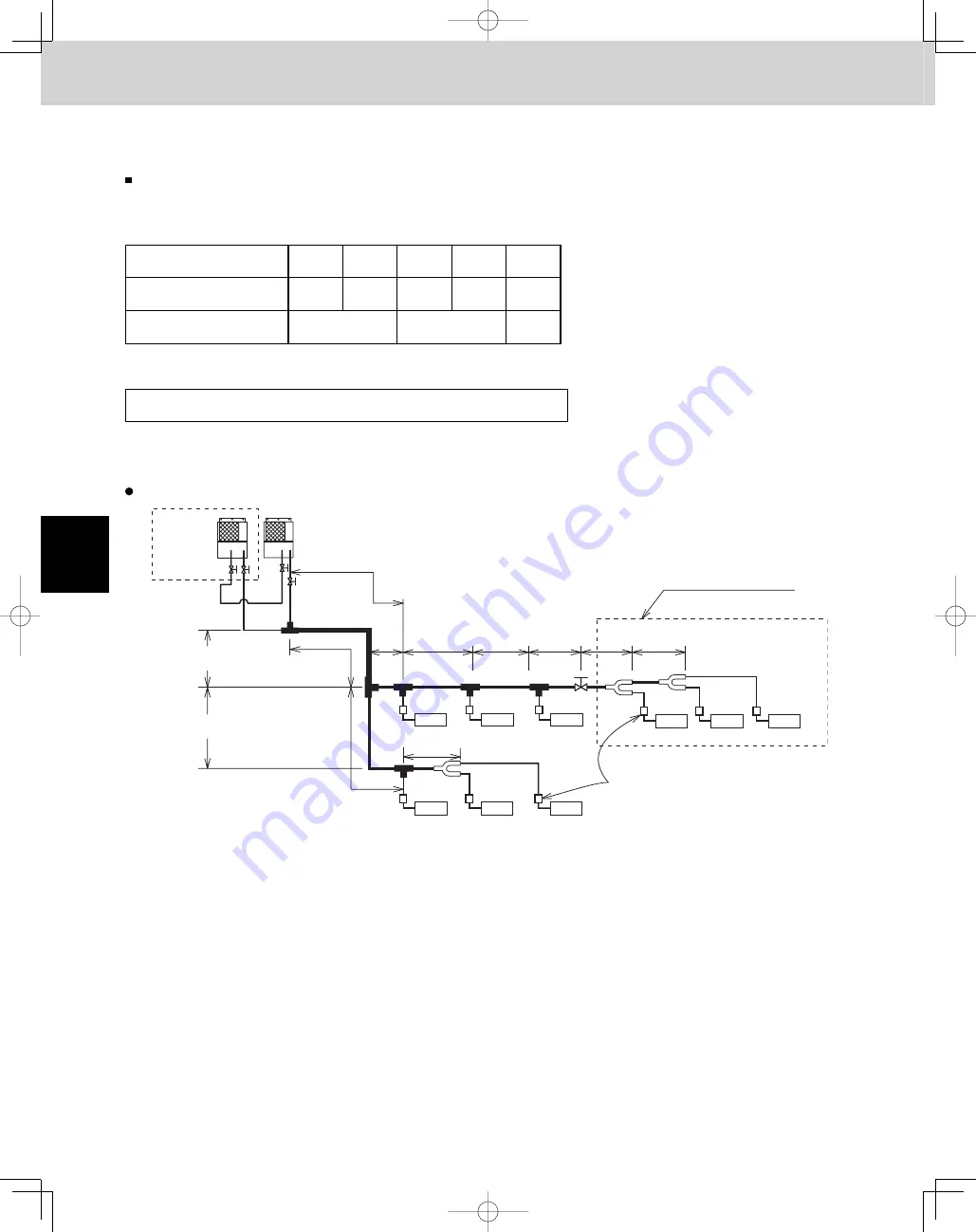
2-2. Example of Tubing Size Selection for Extension and Additional Charge Amount
Sample calculation for the system below
LM
LA
LB
LC
LG
LH
1
LD
LE
LE2
Extension indoor units
Lb
Type 48
Type 18
Type 18
Type 18
Type 36
Type 36
Type 09
Type 18
La
L2
L1
L7
L8
L9
L5
L6
Type 96
Type 96
Elevation difference
H=16.4 ft.
Elevation difference
H=16.4 ft.
Solenoid Valve Kit
Type 36
LF
L4
L3
TD831158-00̲3WAY̲VRF̲SYS.indb 20
TD831158-00̲3WAY̲VRF̲SYS.indb 20
2012/01/23 17:30:15
2012/01/23 17:30:15
Summary of Contents for U-72MF1U9
Page 118: ...Section 8 TENTATIVE ...


