background image

Design of 3WAY VRF SYSTEM

2

 - 23

1

2

3

4

5

6

7

8

2. System Design

Tube branching methods

 (horizontal use)

B

A

B

A

A

B

15 to 30

°

Horizontal

line

View as seen

from arrow

15 to 30

°

Arrow view D

Arrow view C

view D

view C

Ball valve 

(BV: purchased 

separately)

Main tubing

Types of vertical trap specifications

(If only 1 unit is connected, a ball valve 
is also needed on this side.)

Indoor unit (1)

(When not using ball valve)

(When using ball valve)

Branch tubing is 
directed upward.

(Each unit is connected 
to tubing that is either 
level or is directed 
downward.)

Main tubing

 Indoor unit

More than 
7–7/8"

Indoor unit (more than 2 units)

Horizontal

Indoor unit is directed downward

Outdoor

Indoor

Indoor

Indoor

Solidly welded 
shut (X) 

Horizontal 

line

Horizontal 

line

L3  6.56 ft.

Install at a 
positive angle 

Install at a 
positive angle
(15 – 30°)

Header joint system  (Indoor) 

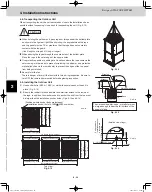
2-3. Installing Distribution Joint

(1)  Refer to “HOW TO ATTACH DISTRIBUTION JOINT” 

enclosed with the optional distribution joint kit (CZ-
P900PH1U, P224BH1U, P680BH1U, P1350BH1U).

(2)  When creating a branch using a commercially available 

T-joint (header joint system), orient the main tubing so that 
it is either horizontal (level) or vertical. In order to prevent 
accumulation of refrigerant oil in stopped units, if the main 
tubing is horizontal then each branch tubing length “B” 
should be at an angle that is greater than horizontal. If the 
main tubing is vertical, provide a raised starting portion for 
each branch.
When only one indoor unit is connected to the side of “A” 
install part “A” at a positive angle (15-30°) for the fi eld tubing 
as shown in the fi gure.


[Header joint system]

  Be sure to solidly weld shut the T-joint end (marked by “X” 

in the fi gure). In addition, pay attention to the insertion 
depth of each connected tube so that the fl ow of refrig-
erant within the T-joint is not impeded. 

  When using the header joint system, do not make fur-

ther branches in the tubing.

  Do not use the header joint system on the outdoor unit 

side.

(3)  If there are height differences between indoor units or if 

branch tubing that follows a distribution joint is connected 
to only 1 unit, a trap or ball valve must be added to that 
distribution joint. (When adding the ball valve, locate it within 
15 - 3/4" of the distribution joint.)


If a trap or ball valve is not added, do not operate the 
system before repairs to a malfunctioning unit are 
completed. (The refrigerant oil sent through the tubing 
to the malfunctioning unit will accumulate and may 
damage the compressor.)

Pay special attention to any 
location, such as a basement, 
etc., where leaking refrigerant 
can accumulate, since 
refrigerant gas is heavier than 
air.

CAUTION

TD831158-00̲3WAY̲VRF̲SYS.indb   23

TD831158-00̲3WAY̲VRF̲SYS.indb   23

2012/01/23   17:30:15

2012/01/23   17:30:15

Summary of Contents for U-72MF1U9

Page 1: ...MK1U6 S 15MM1U6 S 18MM1U6 S 24MF1U6 S 07MP1U6 S 09MP1U6 S 12MP1U6 S 15MP1U6 S 18MP1U6 S 24MP1U6 S 07MR1U6 S 09MR1U6 S 12MR1U6 S 15MR1U6 S 18MR1U6 S 24MR1U6 S 12MT1U6 S 18MT1U6 S 24MT1U6 S 18MK1U6 S 19MS1U6 S 24MK1U6 S 36MF1U6 S 48MF1U6 S 36ME1U6 S 48ME1U6 S 54MF1U6 M1 Y1 F1 U1 D1 T1 E1 P1 R1 K1 7 9 12 15 18 S 24MU1U6 S 36MU1U6 S 12MU1U6 S 18MU1U6 S 12MY1U6 S 18MY1U6 19 1 Section 2 3 4 5 6 7 8 Outd...

Page 2: ...door and outdoor units Get a partner to help and bend your knees when lifting to reduce strain on your back Sharp edges or thin aluminum fins on the air conditioner can cut your fingers When Installing Select an installation location which is rigid and strong enough to support or hold the unit and select a location for easy maintenance In a Room Properly insulate any tubing run inside a room to pr...

Page 3: ...y will not exceed a set limit The refrigerant R410A which is used in the air conditioner is safe without the toxicity or combustibility of ammonia and is not restricted by laws imposed to protect the ozone layer However since it contains more than air it poses the risk of suffocation if its density should rise excessively Suffocation from leakage of refrigerant is almost non existent With the rece...

Page 4: ...anges and performa Tool specifications have been changed due to the characteristics of R410A Some tools for R22 and R407C type refrigerant systems cannot be used Precautions for Installation Using New Refrigerant 1 Care regarding tubing 1 1 Process tubing Material Use C1220 phosphorous deoxidized copper specified in JIS H3300 Copper and Copper Alloy Seamless Pipes and Tubes For tubes of ø7 8 ø22 2...

Page 5: ...t 2 Existing tubing cannot be used especially R22 Completely cleaning out residual refrigerating machine oil is impossible even by flushing 3 Refrigerating machine oil differs R22 Since R22 refrigerating machine oil is mineral oil it does not dissolve in R410A Therefore refrigerating machine oil discharged from the compressor can cause compressor damage R22 refrigerating machine oil Mineral oil Su...

Page 6: ...ng Type P1 Type 11 Concealed Floor Standing Type R1 Type 12 Intaking Fresh Air of 4 Way Casstte Type and Slim Low Static Ducted Type Preparing for Test Run Test Run Procedure Main Outdoor Unit PCB Setting Auto Address Setting Remote Controller Test Run Settings Caution for Pump Down Meaning of Alarm Messages Outdoor Unit Indoor Unit Outdoor Unit Control PCB Indoor Unit Control PCB Switches and Fun...

Page 7: ...6 7 8 Contents 1 Line up 1 2 1 4 1 7 2 Features of 3WAY VRF SYSTEM 3 Salt Air Damage Resistant Specifications 1 OUTLINE OF 3WAY VRF SYSTEM TD831158 00 3WAY VRF SYS indb 1 TD831158 00 3WAY VRF SYS indb 1 2012 01 23 20 13 50 2012 01 23 20 13 50 ...

Page 8: ...ounted K1 Type Low Silhouette Ducted F1 Type Slim Low Static Ducted M1 Type S 07MK1U6 S 09MK1U6 S 12MK1U6 S 07MD1U6 S 09MD1U6 S 12MD1U6 4 Way Cassette U1 Type 4 Way Cassette 60 X 60 Y1 Type Ceiling T1 Type 1 Way Cassette D1 Type S 19MS1U6 High Static Pressure Ducted E1 Type Floor Standing P1 Type Concealed Floor Standing R1 Type S 36ME1U6 S 36MF1U6 S 48MF1U6 S 54MF1U6 S 07MM1U6 S 12MM1U6 S 15MM1U6...

Page 9: ...t model name ended with letters U9E Refer to the Section 1 3 Salt Air Damage Resistant Specifications 96 000 28 1 96 108 000 31 6 Air intake Air intake Air discharge Air intake Air intake 82 9 16 37 1 2 Maximum dimensions 35 Ceiling panel dimensions Air intake Air intake Air discharge Air intake Air intake 82 9 16 37 1 2 Maximum dimensions 35 Ceiling panel dimensions TD831158 00 3WAY VRF SYS indb ...

Page 10: ...ble indoor units Indoor outdoor unit capacity ratio Maximum level difference when outdoor unit is lower Maximum total piping length 164 131 ft If indoor outdoor units need servicing a ball valve field supply cuts off non operational units to let other units stay running If your indoor capacity load changes in the future it s easy to add on both indoor and outdoor units using the same pipings ADDIT...

Page 11: ...e pitch 37 1 2 Maximum dimensions 35 Ceiling panel dimensions 74 Ceiling panel dimensions 4 7 7 8 35 Ceiling panel dimensions 31 1 8 Installation hole pitch 31 1 8 Installation hole pitch 70 1 8 Installation hole pitch 35 Ceiling panel dimensions 35 Ceiling panel dimensions 113 Ceiling panel dimensions 35 Ceiling panel dimensions 4 4 35 Ceiling panel dimensions 36 1 4 Installation hole pitch 37 1 ...

Page 12: ...e of 24 Ton system Capacity Ton 24 20 16 12 8 4 DC1 DC2 AC1 AC2 AC3 DC1 DC1 DC2 DC3 DC1 DC2 DC3 AC1 DC1 DC2 AC2 AC1 DC2 LOAD Example of 3 unit connection Unit 1 AC1 DC1 Unit 2 AC2 DC2 Unit 3 AC3 DC3 DC3 DC3 Capacity control is possible smoothly with a DC inverter compressor The right graph shows the image of the operating combination of compres sors in case of 24 Ton system In actual operation the...

Page 13: ...eatment Urethane coating Fixing bracket Hot dip zinc coated steel sheet Hot dip zinc coated steel sheet Hot dip zinc coated steel sheet Polyester powder double coating both sides m 120 Relevant Parts Material Standard Specifications Salt Air Damage Resistant Specifications Outdoor unit model name ended with letters U9E Outer box side plate drain pan between the stud Base frame Fan guard No treatme...

Page 14: ... MEMO 1 8 TD831158 00 3WAY VRF SYS indb 8 TD831158 00 3WAY VRF SYS indb 8 2012 01 23 20 13 51 2012 01 23 20 13 51 ...

Page 15: ... for Power Supply System 2 24 3 1 General Precautions on Wiring 2 25 3 3 Wiring System Diagrams 2 28 3 4 Important Note When Wiring for Common Type 2 31 3 5 Important Note When Wiring for Y1 Type 2 32 4 Installation Instructions 4 6 Dimensions of Wind Ducting 2 35 Reference diagram for snow proof ducting field supply 2 32 4 1 Selecting the Installation Site for Outdoor Unit 2 33 2 4 Removing Fin G...

Page 16: ...1 50 59 68 77 Indoor air intake temp F DB Operating range 50 59 68 77 86 68 77 86 95 59 68 77 86 95 5 4 14 23 32 41 50 59 68 77 Outdoor air intake temp F WB Operating range Cooling Heating 75 Outdoor air intake temp F DB Outdoor air intake temp F WB Indoor air intake temp F WB Indoor air intake temp F DB TD831158 00 3WAY VRF SYS indb 2 TD831158 00 3WAY VRF SYS indb 2 2012 01 23 17 30 10 2012 01 23...

Page 17: ...orrection coefficient to calcu late the actual capacity for each indoor unit 2 12 Recheck of the actual capacity for each indoor unit If the capacity is inadequate reexamine the unit combinations Example 1 Increasing the outdoor unit capacity 2 18 Example 2 Increasing the indoor unit capacity 2 19 Increasing the tubing size 2 20 Design of tubing Create a tubing design which minimizes the amount of...

Page 18: ...y 1 rank for the suction tubes and discharge tubes field supplied For the portion that exceeds 164 feet set based on the main tube sizes LA listed in the table on the following page Total max tubing length including length of each distribution tube only liquid tubing 1 3 Tubing Length Select the installation location so that the length and size of refrigerant tubing are within the allowable range ...

Page 19: ...rom the liquid tubing total length as follows Amount of Refrigerant Charge Per ft According to Liquid Tubing Size Liquid tubing size Amount of refrigerant in mm charge oz ft ø1 4 ø6 35 0 279 ø3 8 ø9 52 0 602 ø1 2 ø12 7 1 38 ø5 8 ø15 88 1 99 ø3 4 ø19 05 2 78 ø7 8 ø22 22 3 93 Required amount of additional refrigerant charge Amount of additional refrigerant charge per ft of each size of liquid tube i...

Page 20: ...main tube sizes after the branch If the total capacity of the indoor units con nected to the tube ends is different from the total capacity of the outdoor units then the main tube size is selected based on the total capacity of the outdoor units For LA LB and LF in particular ø28 58 ø15 88 ø19 05 ø22 22 ø12 70 24 200 85 300 54 600 54 600 85 300 334 400 ø19 05 102 400 124 200 124 200 143 300 ø22 22...

Page 21: ...4 36 48 54 ø5 8 ø15 88 ø1 2 ø12 7 ø3 8 ø9 52 Gas tubing Liquid tubing ø1 2 ø12 7 ø1 4 ø6 35 ø5 8 ø15 88 ø3 8 ø9 52 Table 2 6 Indoor Unit Tubing Connection Size 1 40 Table 2 7 Refrigerant tubing Existing tubing can be used Distribution joint solenoid valve kit tubing Solenoid valv kit Indoor unit tubing connection over t5 128 t1 0 over t3 64 t1 15 over t3 64 t1 20 Tubing size in mm When bending the...

Page 22: ...city 19 000 If the capacity range is exceeded use 2 solenoid valves connected in parallel 2 When adding ball valve for outdoor unit 1 Location Install the ball valve at the main tube of the distribution joint 2 Installation requirements Be sure to install the ball valve up grade to prevent the inadvertent flow of oil If the ball valve is installed at the outdoor unit including extension for outdoo...

Page 23: ...1 4 7 5 1 5 6 7 4 Trap bend 7 5 9 2 10 5 12 5 14 1 15 4 19 2 Y branch distribution joint Equivalent length conversion not needed Ball valve for service Equivalent length conversion not needed 1 6 Straight Equivalent Length of Joints Design the tubing system by referring to the following table for the straight equivalent length of joints Table 2 8 Straight Equivalent Length of Joints Unit ft TD8311...

Page 24: ...tioner in a room it is neces sary to ensure that if the refrigerant gas accidentally leaks out its density does not exceed the limit level for that room CAUTION Pay special attention to any location such as a basement etc where leaking refrigerant can accumulate since refrig erant gas is heavier than air Check of limit density TD831158 00 3WAY VRF SYS indb 10 TD831158 00 3WAY VRF SYS indb 10 2012 ...

Page 25: ...cooling capacity 5 is greater than 100 then the outdoor unit corrected cooling capacity 5 is considered to be 100 Corrected cooling capacity of each indoor unit 5 Rated cooling capacity for that indoor unit Correction coefficient for indoor temperature conditions at that indoor unit 2 Page 2 14 Distribution ratio based on tubing length and elevation dif ference at that indoor unit 3 Page 2 14 Howe...

Page 26: ...r unit cooling capacity If the corrected outdoor unit cooling capacity is greater than or equal to the total corrected unit cooling capacity of all indoor units in that system Ruc 1 then Actual cooling capacity of each indoor unit 7 Corrected cooling capacity of each indoor unit 5 In other words the cor rection coefficient 6 based on the corrected indoor outdoor capacity ratios for each indoor uni...

Page 27: ...68 77 86 95 104 113 80 90 100 110 120 Outdoor unit heating capacity characteristics Rate of heating capacity change 4 5 14 23 32 41 50 59 40 50 60 70 80 90 100 110 120 5 Graph of capacity correction coefficients Graph of outdoor unit capacity characteristics 1 2 Outdoor air intake temp F DB Outdoor air intake temp F WB Outdoor unit heating capacity correction coefficient during frosting defrosting...

Page 28: ...The negative side indicates the opposite The capacity loss that is caused by the tubing length can be reduced by increasing the sizes of the discharge tubes and suc tion tubes Refer to Table 2 9 and make the appropriate changes However be sure that the total length does not exceed the maximum The only sizes which can be increased are the LM main tube with the largest diameter gas tubes and the cha...

Page 29: ...60 50 4 5 14 23 32 41 50 59 61 70 79 61 70 79 Indoor air intake temp F DB 4 5 14 23 32 41 50 59 130 120 100 90 80 70 60 50 40 130 120 100 90 80 70 60 50 61 70 79 61 70 79 Indoor air intake temp F DB Capacity ratio Input ratio Capacity ratio Input ratio 110 110 110 110 110 110 Heating capacity correction coefficients for frost defrost operation Outdoor intake air temp F WB RH85 4 5 14 17 21 23 24 2...

Page 30: ...nd to be 97 2 Because the calculation result exceeds 97 2 the capacity change rate is 97 2 31 6kW 97 2 30 7kW Heating capacity is 105 000 BTU h 30 7 kW Equivalent length ft Heating Base capacity change rate 164 131 98 66 33 0 33 66 98 131 0 33 66 98 131 164 197 230 262 295 328 361 394 427 459 492 Elevation difference ft 96 000 BTU h 97 2 105 000 BTU h 108 000 BTU h 1 10 Capacity Correction Graph A...

Page 31: ...when the size of the gas tube LM is increased Standard tube diameter gas tube in mm ø1 2 ø12 7 ø5 8 ø15 88 ø3 4 ø19 05 ø7 8 ø22 22 ø1 1 8 ø28 58 Tube diameter after change gas tube in mm ø5 8 ø15 88 ø3 4 ø19 05 ø7 8 ø22 22 ø1 1 8 ø28 58 ø1 3 8 ø34 92 Equivalent length correction coefficient 0 4 0 5 0 6 When increasing the size of the suction and discharge tubing LM multiply by the correction coeff...

Page 32: ...on DB WB Max load BTU h Air condition DB WB Max load BTU h Actual tubing length Equivalent length with consideration for curves etc Equivalent length after size up correction Selected model Load cooling heating BTU h Rated capacity cooling heating BTU h 7 Actual capacity cooling heating BTU h Total corrected capacity of indoor units cooling heating 143 323 59 161 362 40 Ruc 143 323 59 147 532 93 0...

Page 33: ...ing capacity of each indoor unit In other words the correction coefficient 6 for the corrected capacity ratio is 1 96 96 Type 54 Type 36 Type 36 Type 24 192 000 216 000 50 000 55 000 54 600 00 61 400 00 168 609 06 173 189 02 54 600 61 400 54 600 00 61 768 40 30 000 35 000 35 781 01 39 000 00 36 000 39 000 35 781 01 39 234 00 30 000 35 000 34 941 99 39 000 00 36 000 39 000 34 941 99 39 234 00 18 50...

Page 34: ...ø3 4 ø19 05 ø7 8 ø22 22 ø1 1 8 ø28 58 ø1 3 8 ø34 92 Equivalent length correction coefficient 0 4 0 5 0 6 When increasing the size of the suction and discharge tubing LM multiply by the correction coefficient from Table 2 11 and calculate the equivalent length for section LM Tubing equivalent length after size increase Standard tubing equivalent length Equivalent length correction coefficient 2 2 E...

Page 35: ...ional refrigerant charge after extension Liquid tube diameter Tubing length ft A Additional refrigerant charge per 1 ft oz ft B A B oz LE2 ø3 8 13 1 0 602 7 900 LF ø3 8 16 4 0 602 9 875 L4 ø3 8 13 1 0 602 7 900 L5 ø3 8 19 7 0 602 11 850 L6 ø1 4 23 0 0 279 6 407 Total oz 43 934 44 oz Calculation of additional refrigerant charge for the entire 3WAY VRF system Additional refrigerant charge for entire...

Page 36: ...m it is necessary to ensure that even if the refrigerant gas accidentally leaks out its density does not exceed the limit level for that room Always check the gas density limit for the room in which the unit is installed WARNING TD831158 00 3WAY VRF SYS indb 22 TD831158 00 3WAY VRF SYS indb 22 2012 01 23 17 30 15 2012 01 23 17 30 15 ...

Page 37: ...horizontal then each branch tubing length B should be at an angle that is greater than horizontal If the main tubing is vertical provide a raised starting portion for each branch When only one indoor unit is connected to the side of A install part A at a positive angle 15 30 for the field tubing as shown in the figure Header joint system Be sure to solidly weld shut the T joint end marked by X in ...

Page 38: ...before beginning You must ensure that installation complies with all rel evant rules and regulations 8 To prevent malfunction of the air conditioner caused by electrical noise care must be taken when wiring as fol lows The remote control wiring and the inter unit control wiring should be wired apart from the inter unit power wiring Use shielded wires for inter unit control wiring between units and...

Page 39: ...odel S 07MK1U6 S 09MK1U6 S 12MK1U6 K1 Type Model S 18MK1U6 S 19MS1U6 S 24MK1U6 4P terminal board L1 L2 L3 1 2 3 4 4P terminal board Inter outdoor unit control wiring Inter unit control wiring Outdoor Unit 2 1 2 1 2 1 B C A L1 L2 L1 L2 L1 L2 L1 L2 2 1 A B A A U2 U1 L2 L1 R2 R1 U2 U1 L2 L1 R2 R1 U2 U1 L2 L1 R2 R1 U2 U1 L2 L1 2 1 B 1 3 Remote Controller CONNECTOR 2P WHT RC BLU WHT BLK WHT BLK WHT BLK...

Page 40: ...unit Indoor unit Indoor unit Indoor unit Fig 2 1 3 Do not install inter unit control wiring such as star branch wiring Star branch wiring causes mis address setting Fig 2 2 Outdoor unit Indoor unit Indoor unit Indoor unit Indoor unit NO Branch point Fig 2 2 4 If branching the inter unit control wiring the number of branch points should be 16 or fewer Branches less than 3 3 ft are not included in t...

Page 41: ...minal plate For stranded wiring 1 insulation to expose the stranded wiring approx 3 8 and tightly twist the wire ends Fig 2 4 2 terminal screw s on the terminal plate 3 clamp each stripped wire end with a ring pressure terminal 4 Cut the wire end with cutting pliers then strip the Using a Phillips head screwdriver remove the Using a ring connector fastener or pliers securely Place the ring pressur...

Page 42: ...each other and not to leave the wirings loose When loosening the clamping clip twist the strap and it will come undone Securely affix the 3 way wiring harness with the remote control wiring U1 type NOTE 1 2 3 Earth screw Power wiring field supplied Connection for Solenoid Valve Kit for 3WAY Remote control wiring and Inter unit control wiring field supplied Clamping clip Conduit U1 Type Remote cont...

Page 43: ... supplied Clamping clip Conduit field supplied Remote control wiring field supplied Connection for Solenoid Valve Kit for 3WAY Remote control wiring and Inter unit control wiring field supplied Earth screw Power wiring field supplied Clamping clip Conduit field supplied Clamping clip Power wiring field supplied Earth screw Conduit Optional remote control wiring field supplied 3 way connection wiri...

Page 44: ...supplied Clamping strap Connection for Solenoid Valve Kit for 3WAY Conduit field supplied Power wiring field supplied Remote control wiring and Inter unit control wiring field supplied Clamping strap Connection for Solenoid Valve Kit for 3WAY Model S 18MK1U6 S 19MS1U6 S 24MK1U6 Earth screw Necessary to install the External Electronic Expansion Valve Kit Optional CZ P56SVK1U TD831158 00 3WAY VRF SY...

Page 45: ...rounding conductor of the incoming power supply to the earth ground screw before connecting the power supply conductors to L1 L2 of the terminal block Securely affix the two power supply conductors L1 L2 in the wiring channel by the clamping strap as shown NOTE Take care not to damage the control wirings by the clasp Do not leave the control wirings loose Connection for Solenoid Valve Kit for 3WAY...

Page 46: ...cause this space is needed as a servicing space for the compressor Ensure a base height of 4 in or more to ensure that drainage water does not accumulate and freeze around the bottom of the unit If installing a drain pan install the drain pan prior to installing the outdoor unit Make sure there is at least 6 in between the outdoor unit and the ground Also the direction of the tubing and electrical...

Page 47: ...utdoor Unit in Heavy Snow Areas In locations where wind blown snow can be a problem snow proof ducting field supply should be fitted to the unit and direct exposure to the wind should be avoided as much as possible Fig 2 11 The following problems may occur if proper countermeasures are not taken The fan in the outdoor unit may stop running causing the unit to be damaged There may be no air flow Th...

Page 48: ... 7 8 7 7 8 36 1 4 Installation hole pitch 2 1 35 Ceiling panel dimensions 3 unit installation Installation hole pitch 31 1 8 Installation hole pitch 31 1 8 Installation hole pitch Air direction Front direction Air direction Right direction unit in unit in Maximum bracket dimensions Maximum bracket dimensions Front view Right side view Front view Right side view Can be installed so that the air dir...

Page 49: ...5 8 53 5 8 53 5 8 9 1 2 9 1 2 7 8 2 1 8 44 3 8 44 3 8 44 3 8 31 1 8 131 3 4 31 1 8 31 1 8 35 36 1 4 37 3 8 35 Ceiling panel dimensions 31 1 2 Air intake duct 3 unit installation Air discharge chamber Field supply 31 1 2 unit in unit in Front direction Air intake duct Front view Right side view Right side view Front view Can be installed so that the air direction is to the front right left or rear ...

Page 50: ... the installation anchor holes Figs 2 13 and 2 14 Fig 2 13 Fig 2 14 3 15 16 3 15 16 3 15 32 25 32 1 31 32 Washer Plate leg Base Anchor bolts Vibration insulator CAUTION 1 33 64 19 32 1 31 32 4 19 32 25 32 hole Detailed view of legs Surface where installation anchor brackets are installed Unit in Unit in The vibration insulator base or platform must be large enough to bear the full surface of the b...

Page 51: ...herefore remove the front panel Fig 2 17 1 If the tubing is routed out from the front use cutting pliers or a similar tool to cut out the tubing outlet slit part indicated by from the tubing cover Figs 2 17 and 2 18 2 If the tubing is routed out from the bottom remove the slit part Use a drill bit approximately 13 64 dia to create holes at the 4 slit hole indentations openings Punch out the slit p...

Page 52: ...ess Outer dia Thickness ø1 4 ø6 35 t1 32 t0 8 ø3 4 ø19 05 over t5 128 t1 0 ø3 8 ø9 52 t1 32 t0 8 ø7 8 ø22 22 t5 128 t1 0 ø1 2 ø12 7 t1 32 t0 8 ø1 1 8 ø28 58 t5 128 t1 0 ø5 8 ø15 88 t5 128 t1 0 ø1 3 8 ø34 92 over t3 64 t1 1 4 13 Connect the Tubing Use the supplied connector tubing See figure below 1 2 3 4 72 type 6 Ton 96 type 8 Ton 1 2 3 4 Refrigerant tube port Use caulking putty or a similar mate...

Page 53: ...stalling the flare nuts Doing so may damage the valve Do not apply an adjustable wrench to the hexagonal part Do not use two adjustable wrenches when removing or installing the balance tube flare nut In particular do not apply an adjustable wrench to the hexagonal part at the top of the valve If force is applied to this part gas leakage will occur 2 If the valve cap is left off for a long period o...

Page 54: ...prox 1 2 ft longer than the tubing length you estimate Remove burrs at the end of the copper tube with a tube reamer or file This process is important and should be done carefully to make a good flare Fig 2 19 NOTE When reaming hold the tube end downward and be sure that no copper scraps fall into the tube Fig 2 20 3 4 Remove the flare nut from the unit and be sure to mount it on the copper tube M...

Page 55: ...flare nuts apply specified torque as at right When removing the flare nuts from the tubing connections or when tightening them after connecting the tubing be sure to use 2 adjustable wrenches or spanners as shown Fig 2 24 If the flare nuts are over tightened the flare may be damaged which could result refrigerant leakage and cause in injury or asphyxiation to room occupants For the flare nuts at t...

Page 56: ...nels to be attached and removed Taping the flare nuts Wind the white insulation tape around the flare nuts at the gas tube connections Then cover up the tubing connections with the flare insulator and fill the gap at the union with the supplied black insulation tape Finally fasten the insulator at both ends with the supplied vinyl clamps Fig 2 26 Two tubes arranged together Liquid tubing Gas tubin...

Page 57: ...ers the wall As you wrap the tubing overlap half of each previous tape turn Clamp the tubing bundle to the wall using 1 clamp approx each ft Fig 2 27 NOTE Do not wind the armoring tape too tightly since this will decrease the heat insulation effect Also ensure that the condensation drain hose splits away from the bundle and drips clear of the unit and the tubing 5 5 Finishing the Installation Afte...

Page 58: ...b Manifold gauge Outlet Inlet Vacuum pump Fig 2 31 Manifold valve Pressure gauge Lo Hi Charge hose Outdoor unit Close Open Discharge tube Suction tube Liquid tube Nitrogen gas cylinder In vertical standing position Close Close Open Balance tube Open Close Open Cylinder valve Leak test 1 Attach a manifold valve with pressure gauges and dry nitrogen gas cylinder to all service ports with charge hose...

Page 59: ...n the vacuum pump The operation time for evacuation varies with the tubing length and capacity of the pump The following table shows the amount of time for evacuation Required time for evacuation when 30 gal h vacuum pump is used If tubing length is less than 49 ft If tubing length is longer than 49 ft 45 min or more 90 min or more Evacuation is not necessary for the balance tube if only 1 outdoor...

Page 60: ...2 34 Close the valve on the cylinder containing R410A Finishing the job 1 2 3 4 5 With a flathead screwdriver turn the liquid tube service valve counter clockwise to fully open the valve Turn the all service valve counter clockwise to fully open the valve Close all stop valves and loosen the Lo knob of the manifold valve Loosen the charge hose connected to all service port then remove the hose Rep...

Page 61: ...tubing will not be possible if the tube shape is not proper Cut off as far away from stopper as possible After cutting the joints be sure to remove burrs on the inside of the joints If the joints have been squashed or dented badly reshaped them using a tube spreader Make sure there is no dirt or other foreign substances inside the distribution joint Size of connection point on each part Shown are ...

Page 62: ...oor unit Outdoor unit Direction of Distribution Joint Direction of Distribution Joint Indoor unit When brazing replace air inside the tube with nitrogen gas to prevent copper oxide from forming To insulate the distribution joint use the supplied tubing insulation If using insulation other than that supplied make sure that its heat resistance is 248 F or higher For additional details refer to the i...

Page 63: ...id Tube Discharge Tube G G H E F D E F F E D C D D C C E F G F E G F E E F G F E D C D F E USE For indoor unit Capacity after distribution joint is greater than 22 4kW and no more than 68 0kW H I H I H I Insulation Insulation Insulation Unit mm G GH 300 300 340 G GH USE For Indoor unit Capacity after distribution joint is 22 4kW or less Suction Tube H I I H H F F H G G G G F H H H Liquid Tube Liqu...

Page 64: ...ize selection of the tube diameter refer to the installation instructions provided with the outdoor unit Insertion length of the connecting tube Make this as long as possible Make sure there is no dirt or other foreign substances inside the distribution joint To insulate the distribution joint use the supplied tubing insulation If using insulation other than that supplied make sure that its heat r...

Page 65: ...ON 1 Accessories Part Name Figure Q ty Remarks Washer Hanging hook M4 screw L 15 32 For hanging bolts Used to hang the Solenoid Valve Kit For hanging hook Tapping screw L 5 16 For Solenoid Valve Relay Kit Wire holder ACC 3WAY AAB 3 Way connect wire 6 5ft For Solenoid Valve Relay Kit wiring Solenoid Valve Relay Kit 4 4 1 1 1 1 2 2 Positioning for Installation The solenoid valve kit produces some re...

Page 66: ... with the top surface facing upward See the figure shown in the subsection How to use the fittings in 3 Valve Dimensions and Hanging Method Provide a service space of 7 7 8 or more in front of the installing site Never conduct drilling or welding on the sheet metal Place the solenoid valve kit so that it does not hinder draining Do not cover air holes Service space 5 55 64 53 64 2 63 64 9 29 64 63...

Page 67: ...flame and heat conduction Comply with all Local Code Requirements Clean base metals throughly Use proper ventilation to carry fumes away from the work area Use a high quality silver based solder of at least 15 silver Heat the base materials broadly and uniformly Take precautions not to overheat the device which could damage sensitive internal components Insure compliance with all local codes Be su...

Page 68: ...enoid valve kit to the solenoid valve relay kit using the Class wire 3 Connect the solenoid valve relay kit to the indoor unit using the supplied connect wire 4 The left over wires connected to the solenoid valve relay kit should be tied up in a bundle of wires by the supplied wire holder not to leave the wires loose as shown in the diagram at right 5 wires field supplied Class 98ft Max Solenoid v...

Page 69: ...noid valve relay kit Solenoid valve relay kit Tapping screws 4 pcs Bracket Unscrew the tapping screws and remove the bracket Turn 180 degrees upside down Reinstall the bracket with the tapping screws Electrical Wiring Diagrams 6 Only for 3 Way connect wire fix with a clip 3 Way wiring connector TD831158 00 3WAY VRF SYS indb 55 TD831158 00 3WAY VRF SYS indb 55 2012 01 23 17 30 22 2012 01 23 17 30 2...

Page 70: ...ough the eyelet K1 Type For wall mount type K1 type install the solenoid valve relay kit on the wall Important Installation behind the wall or ceiling is required that the maintenance should become capable Solenoid valve relay kit Solenoid valve relay kit TD831158 00 3WAY VRF SYS indb 56 TD831158 00 3WAY VRF SYS indb 56 2012 01 23 17 30 22 2012 01 23 17 30 22 ...

Page 71: ...3 Way connect wire fix with a clip Open the knock out hole and install the eyelet Ø1 3 16 supplied with the indoor unit Then put the 3 way connect wire through the eyelet Open the knock out hole and install the eyelet Ø1 3 16 supplied with the indoor unit Then put the 3 way connect wire through the eyelet TD831158 00 3WAY VRF SYS indb 57 TD831158 00 3WAY VRF SYS indb 57 2012 01 23 17 30 22 2012 01...

Page 72: ... MEMO 2 58 TD831158 00 3WAY VRF SYS indb 58 TD831158 00 3WAY VRF SYS indb 58 2012 01 23 17 30 23 2012 01 23 17 30 23 ...

Page 73: ...te Controller 5 System Controller 6 Schedule Timer 7 Intelligent Controller CZ 256ESMC1U 8 Communication Adaptor CZ CFUNC1U 9 Remote Sensor 10 LonWorks Interface CZ CLNC1U Refer to the 2WAY VRF SYSTEM TECHNICAL DATA TD831157 3 Control of 3WAY VRF SYSTEM TD831158 00 3WAY VRF SYS indb 1 TD831158 00 3WAY VRF SYS indb 1 2012 01 17 16 01 01 2012 01 17 16 01 01 ...

Page 74: ... MEMO 3 2 TD831158 00 3WAY VRF SYS indb 2 TD831158 00 3WAY VRF SYS indb 2 2012 01 17 16 01 01 2012 01 17 16 01 01 ...

Page 75: ...ette Type U1 Type 4 Way Cassette 60 60 Type Y1 Type 1 Way Cassette Type D1 Type Low Silhouette Ducted Type F1 Type Slim Low Static Ducted Type M1 Type High Static Pressure Ducted Type E1 Type Ceiling Type T1 Type Wall Mounted Type K1 Type 10 11 12 Floor Standing Type P1 Type Concealed Floor Standing Type R1 Type Intaking Fresh Air of 4 Way Casstte Type and Slim Low Static Ducted Type Refer to the ...

Page 76: ...ost Heat exchanger Aluminum plate fin Copper tube FAN DEVICE Type Q ty Propeller fan x 1 Air circulation CFM 5 300 External static pressure in WG 0 Motor output No of poles kW 0 7 8P Protective devices High pressure switch overcurrent CT method TUBING Refrigerant tubing Suction tube in mm ø3 4 ø19 05 1 Brazing Discharge tube in mm ø5 8 ø15 88 Brazing Liquid tube in mm ø3 8 ø9 52 Brazing Balance tu...

Page 77: ...ger Aluminum plate fin Copper tube FAN DEVICE Type Q ty Propeller fan x 1 Air circulation CFM 5 650 External static pressure in WG 0 Motor output No of poles kW 0 7 8P Protective devices High pressure switch overcurrent CT method TUBING Refrigerant tubing Suction tube in mm ø7 8 ø22 22 1 Brazing Discharge tube in mm ø3 4 ø19 05 Brazing Liquid tube in mm ø3 8 ø9 52 Brazing Balance tube in mm ø3 8 ø...

Page 78: ...rigerant control Electronic expansion valve Defrost method Reverse cycle defrost outdoor unit cycle defrost Heat exchanger Aluminum plate fin Copper tube FAN DEVICE Type Q ty Propeller fan x 1 Propeller fan x 1 Air circulation CFM 5 300 5 300 External static pressure in WG 0 0 Motor output No of poles kW 0 7 8P 0 7 8P Protective devices High pressure switch overcurrent CT method TUBING Refrigerant...

Page 79: ...t control Electronic expansion valve Defrost method Reverse cycle defrost outdoor unit cycle defrost Heat exchanger Aluminum plate fin Copper tube FAN DEVICE Type Q ty Propeller fan x 1 Propeller fan x 1 Air circulation CFM 5 300 5 650 External static pressure in WG 0 0 Motor output No of poles kW 0 7 8P 0 7 8P Protective devices High pressure switch overcurrent CT method TUBING Refrigerant tubing...

Page 80: ...ol Electronic expansion valve Defrost method Reverse cycle defrost outdoor unit cycle defrost Heat exchanger Aluminum plate fin Copper tube FAN DEVICE Type Q ty Propeller fan x 1 Propeller fan x 1 Air circulation CFM 5 650 5 650 External static pressure in WG 0 0 Motor output No of poles kW 0 7 8P 0 7 8P Protective devices High pressure switch overcurrent CT method TUBING Refrigerant tubing Suctio...

Page 81: ... 8 Refrigerant control Electronic expansion valve Defrost method Reverse cycle defrost outdoor unit cycle defrost Heat exchanger Aluminum plate fin Copper tube FAN DEVICE Type Q ty Propeller fan x 1 Propeller fan x 1 Propeller fan x 1 Air circulation CFM 5 300 5 300 5 300 External static pressure in WG 0 0 0 Motor output No of poles kW 0 7 8P 0 7 8P 0 7 8P Protective devices High pressure switch o...

Page 82: ...rigerant control Electronic expansion valve Defrost method Reverse cycle defrost outdoor unit cycle defrost Heat exchanger Aluminum plate fin Copper tube FAN DEVICE Type Q ty Propeller fan x 1 Propeller fan x 1 Propeller fan x 1 Air circulation CFM 5 650 5 300 5 300 External static pressure in WG 0 0 0 Motor output No of poles kW 0 7 8P 0 7 8P 0 7 8P Protective devices High pressure switch overcur...

Page 83: ...t control Electronic expansion valve Defrost method Reverse cycle defrost outdoor unit cycle defrost Heat exchanger Aluminum plate fin Copper tube FAN DEVICE Type Q ty Propeller fan x 1 Propeller fan x 1 Propeller fan x 1 Air circulation CFM 5 650 5 650 5 300 External static pressure in WG 0 0 0 Motor output No of poles kW 0 7 8P 0 7 8P 0 7 8P Protective devices High pressure switch overcurrent CT...

Page 84: ...ol Electronic expansion valve Defrost method Reverse cycle defrost outdoor unit cycle defrost Heat exchanger Aluminum plate fin Copper tube FAN DEVICE Type Q ty Propeller fan x 1 Propeller fan x 1 Propeller fan x 1 Air circulation CFM 5 650 5 650 5 650 External static pressure in WG 0 0 0 Motor output No of poles kW 0 7 8P 0 7 8P 0 7 8P Protective devices High pressure switch overcurrent CT method...

Page 85: ...3 21 2 05 16 7 22 6 189 000 209 500 123 000 10 6 3 21 2 05 16 4 22 6 164 000 184 000 114 000 10 7 3 21 2 05 16 1 WU 168MF1U9 E 23 3 160 000 178 500 98 000 10 5 3 21 2 05 16 9 23 0 162 000 181 000 106 000 10 6 3 21 2 05 16 5 23 1 139 000 157 000 93 500 10 8 3 21 2 05 16 4 WU 144MF1U9 E 23 8 137 000 151 000 83 500 10 9 3 31 2 25 17 1 23 5 138 000 154 000 88 500 10 9 3 26 2 15 16 8 23 1 95 000 106 50...

Page 86: ... Electrical wiring port bottom ø2 23 64 ø1 1 2 knock out holes for conduit connection Pressure outlet port for high pressure ø5 16 ø7 94 Schrader type connection Pressure outlet port for low pressure ø5 16 ø7 94 Schrader type connection Knock out hole for connecting pressure gauge optional Equivalent tonnage Table of Measurements for Refrigerant Tube Connection Measurements for 8 Ton assume that t...

Page 87: ...tch 109 1 16 Installation hole pitch 6 Ton U 72MF1U9 U 72MF1U9E U 96MF1U9 U 96MF1U9E 8 Ton Equivalent tonnage 18 Ton 20 Ton 22 Ton 24 Ton unit in 35 Ceiling panel dimensions 36 1 4 Installation hole pitch 37 1 2 Maximum dimensions 35 Ceiling panel dimensions 74 Ceiling panel dimensions 4 7 7 8 35 Ceiling panel dimensions 31 1 8 Installation hole pitch 31 1 8 Installation hole pitch 70 1 8 Installa...

Page 88: ...3 5 8 853 Y Z X 13 1 4 336 18 7 8 481 30 1 4 767 U 96MF1U9 U 96MF1U9E Top view in mm unit in 31 1 8 Installation hole pitch 35 Ceiling panel dimensions 36 1 4 Installation hole pitch 37 1 2 Maximum dimensions 35 Ceiling panel dimensions 1 47 64 31 7 64 34 9 16 Front view Right side 8 1 2 82 9 16 31 19 64 74 1 16 TD831158 00 3WAY VRF SYS indb 14 TD831158 00 3WAY VRF SYS indb 14 2011 12 12 17 22 44 ...

Page 89: ... way valve Solenoid valve Solenoid valve Outside air Electronic control valv Electronic control valve Fusible plug U 96MF1U9 U 96MF1U9E Solenoid valve Oil separator Oil drain High pressure switch Low pressure sensor o be brazed pinch after oil is inserted 1 portion Thermistor position Solenoid valve Balance tube ø3 8 flare connection Suction tube ø7 8 Brazing Use supplied only Discharge tube ø3 4 ...

Page 90: ...250 500 1000 2000 4000 8000 Frequency at center of octave band Hz Standard mode Quiet mode 60Hz MODEL CONDITION SOUND LEVEL dB A Cooling Heating U 96MF1U9 U 96MF1U9E 3 3 ft in front at height of 4 9 ft 55 0 Quiet mode 52 0 Octave Band Level dB 70 60 50 40 30 20 Overall Approximate minimum audible limit for continuous noise 63 125 250 500 1000 2000 4000 8000 Frequency at center of octave band Hz St...

Page 91: ...un Procedure 5 3 3 Main Outdoor Unit PCB Setting 5 4 4 Auto Address Setting 5 6 5 Remote Controller Test Run Settings 5 12 6 Caution for Pump Down 5 12 7 Meaning of Alarm Messages 5 13 TD831158 00 3WAY VRF SYS indb 1 TD831158 00 3WAY VRF SYS indb 1 2012 01 24 10 54 18 2012 01 24 10 54 18 ...

Page 92: ...other 3 tubes suction discharge and liquid tubes Fig 5 2 If 2 or 3 outdoor units are installed open the service valves on all 4 tubes suction discharge liquid and bal ance tubes Fig 5 2 5 Request that the customer be present for the trial run Explain the contents of the instruction manual then have the customer actually operate the system 6 Be sure to give the instruction manual and warranty cer t...

Page 93: ...heating operation LED 1 and 2 blink alternately LED 1 and 2 blink alternately about 2 or 3 minutes Is it OK to start the compressors Turn ON the indoor and outdoor unit power Turn OFF the indoor and outdoor unit power Turn ON the indoor and outdoor unit power for that refrigerant system only Are LEDs 1 and 2 on the outdoor unit PCB OFF Are LEDs 1 and 2 on the outdoor unit PCB OFF Set the unit addr...

Page 94: ...nits System address No Indoor unit setting S005 3P DIP switch blue Indoor unit setting S004 Rotary switch red System address S003 2P DIP switch blue System address S002 Rotary switch black System 1 factory setting 1 unit factory setting 11 units 21 units 31 units All OFF No of outdoor units Outdoor unit setting S006 3P DIP switch blue Address setting of outdoor unit S007 3P DIP switch blue 1 unit ...

Page 95: ...5 5 1 2 3 4 5 6 7 8 3 Main Outdoor Unit PCB Setting Fig 5 4 CN003 CN101 CN100 S002 S003 S004 S005 S007 S006 TD831158 00 3WAY VRF SYS indb 5 TD831158 00 3WAY VRF SYS indb 5 2012 01 24 10 54 20 2012 01 24 10 54 20 ...

Page 96: ...t the unit No switch S007 to On the No 3 sub unit control PCB set the unit No switch S007 to On the outdoor main unit control PCB check that the system address rotary switch S002 is set to 1 and that the DIP 0 These are the settings at the time of factory shipment switch S003 is set to To set the number of indoor units that are connected to the outdoor unit to 10 on the outdoor main unit control P...

Page 97: ...o of indoor units 13 units setting System address system 1 setting Outdoor unit system 1 Indoor unit Remote controller Inter unit control wiring No 2 Refrigerant circuit No 1 main unit settings System address system 2 setting No of indoor units 9 units setting No of outdoor units 2 units setting Unit number setting unit No 1 No 2 sub unit settings Unit number setting unit No 2 No 1 Outdoor unit sy...

Page 98: ...ress pin CN100 for 1 second or longer then release it The LED that indicates automatic address setting is in progress turns OFF and the process is stopped Be sure to perform automatic address setting again Short circuit the automatic address pin at the outdoor main unit CN100 for 1 second or longer then release it Turn on power to all indoor and outdoor units in the system and set the rotary switc...

Page 99: ...ommunication for automatic address setting begins the compressors turn ON and automatic address setting in Heating mode begins All indoor units operate To cancel again short circuit the automatic address pin CN100 for 1 second or longer then release it The LED that indicates automatic address setting is in progress turns OFF and the process is stopped Be sure to perform automatic address setting a...

Page 100: ...rn OFF At the outdoor main unit in the next different system short circuit the automatic address pin CN100 for 1 second or longer then release it Repeat the same steps to complete automatic address setting for all units Operation from the remote controllers is now possible Automatic address setting in Cooling mode cannot be done from the remote controller Automatic Address Setting from the Remote ...

Page 101: ...rned ON and automatic address setting is not in progress no communication with the indoor units in that system is possible After the power is turned ON and automatic address setting is not in progress 1 or more indoor units are confirmed in that system however the number of indoor units does not match the number that was set Alternating Alternating Automatic address setting is in progress Automati...

Page 102: ... mode 5 Remote Controller Test Run Settings 1 Press the remote controller button for 4 seconds or longer Then press the button TEST appears on the LCD display while the test run is in progress The temperature cannot be adjusted when in Test Run mode This mode places a heavy load on the machines Therefore use it only when per forming the test run 2 The test run can be performed using the HEAT COOL ...

Page 103: ...unit The number of connected main and sub outdoor units do not correspond to the number set at main outdoor unit PCB Error of main indoor unit in receiving serial communication signal from sub indoor units Error of sub outdoor unit in receiving serial communication signal from main outdoor unit No indoor unit is connected during auto address setting Error in auto address setting Number of connecte...

Page 104: ...emperature Comp No 2 Outdoor unit fan motor is unusual Overcurrent at time of compressor runs more than 80Hz DCCT secondary current or ACCT primary current is detected at a time other than when IPM has tripped IPM trip IPM current or temperature Inverter for compressor is unusual DC compressor does not operate Indoor coil temp sensor E1 Indoor coil temp sensor E2 Indoor coil temp sensor E3 Indoor ...

Page 105: ...ng correctly Mis wiring of control wiring between indoor unit main outdoor unit and system controller CN1 is not connected properly When using wireless remote controller or system controller in order to check the alarm message in detail connect wired remote controller to indoor unit temporarily Error in transmitting serial communication signal Error in receiving serial communication signal Protect...

Page 106: ... MEMO 5 16 TD831158 00 3WAY VRF SYS indb 16 TD831158 00 3WAY VRF SYS indb 16 2012 01 24 10 54 23 2012 01 24 10 54 23 ...

Page 107: ...it 6 2 6 2 6 4 1 Electric Wiring Diagram U 72MF1U9 U 72MF1U9E 2 Electric Wiring Diagram U 96MF1U9 U 96MF1U9E 2 Indoor Unit Refer to the 2WAY VRF SYSTEM TECHNICAL DATA TD831157 TD831158 00 3WAY VRF SYS indb 1 TD831158 00 3WAY VRF SYS indb 1 2011 11 07 9 11 17 2011 11 07 9 11 17 ...

Page 108: ...Electrical Data 6 2 8 7 6 5 4 3 2 1 1 Outdoor Unit 1 Electric Wiring Diagram U 72MF1U9 U 72MF1U9E TD831158 00 3WAY VRF SYS indb 2 TD831158 00 3WAY VRF SYS indb 2 2011 11 07 9 11 18 2011 11 07 9 11 18 ...

Page 109: ...Electrical Data 6 3 1 2 3 4 5 6 7 8 1 Outdoor Unit Schematic Diagram U 72MF1U9 U 72MF1U9E TD831158 00 3WAY VRF SYS indb 3 TD831158 00 3WAY VRF SYS indb 3 2011 11 07 9 11 18 2011 11 07 9 11 18 ...

Page 110: ...Electrical Data 6 4 8 7 6 5 4 3 2 1 1 Outdoor Unit 2 Electric Wiring Diagram U 96MF1U9 U 96MF1U9E TD831158 00 3WAY VRF SYS indb 4 TD831158 00 3WAY VRF SYS indb 4 2011 11 07 9 11 18 2011 11 07 9 11 18 ...

Page 111: ...Electrical Data 6 5 1 2 3 4 5 6 7 8 1 Outdoor Unit Schematic Diagram U 96MF1U9 U 96MF1U9E TD831158 00 3WAY VRF SYS indb 5 TD831158 00 3WAY VRF SYS indb 5 2011 11 07 9 11 18 2011 11 07 9 11 18 ...

Page 112: ...l PCB CR CHDZ09663 1 2 Outdoor Unit Filter PCB FIL CHDX14053 1 3 Outdoor Unit HIC Board HIC CHDX14053 1 4 Functions for CR CHDZ09663 2 Indoor Unit Control PCB Switches and Functions Refer to the 2WAY VRF SYSTEM TECHNICAL DATA TD831157 TD831158 00 3WAY VRF SYS indb 1 TD831158 00 3WAY VRF SYS indb 1 2012 01 23 17 29 23 2012 01 23 17 29 23 ...

Page 113: ...6 plug High pressure sensor RC1 CN106 plug Outdoor air temp Comp discharge 3 temp Gas temp sensor at heat exchanger 1 2 Comp discharge 2 temp Comp discharge 1 temp Liquid temp sensor at heat exchanger 1 2 CT2 CT3 Gas temp and Liquid temp sensor at heat exchanger 3 CTL1 CTL2 Oil detection sensor Suction temp HIC2 HIC1 HIC3 Power LED D53 EEPROM memory IC IC018 Alarm LED LED1 2 S006 S010 S007 S004 S0...

Page 114: ... 3 4 5 6 7 8 1 Outdoor Unit Control PCB 1 2 Outdoor Unit Filter PCB FIL CHDX14053 1 3 Outdoor Unit HIC Board HIC CHDX14053 TD831158 00 3WAY VRF SYS indb 3 TD831158 00 3WAY VRF SYS indb 3 2012 01 23 17 29 23 2012 01 23 17 29 23 ...

Page 115: ... If 10 systems or more are set the setting is made by a combination of this DIP switch and S002 If 10 19 systems are set set switch 1 10s digit to ON If 20 29 systems are set set switch 2 20s digit to ON and set switch 1 10s digit to OFF If 30 systems are set set both switch 1 10s digit and switch 2 20s digit to ON For details concerning S002 and S003 refer to Table 7 1 S004 Rotary switch 10 posit...

Page 116: ...is pin and apply a pulse signal to stop all indoor units in that refrigerant system AP CN102 2P plug white Vacuuming pin To perform vacuuming of the outdoor unit short circuit this pin and then turn the power ON All solenoid valves turn ON and vacuuming begins smoothly Do not perform automatic address setting at this time Release the short circuit to return the unit to normal status Mode CN101 2P ...

Page 117: ...ON ON ON ON ON ON ON ON 30 0 ON ON Table 7 2 Setting the Number of Indoor Units S004 Rotary switch red S005 2P DIP blue Number of Indoor Units S004 Setting S005 Setting 1 2 3 1 1 OFF OFF OFF 2 2 OFF OFF OFF 3 3 OFF OFF OFF 9 9 OFF OFF OFF 10 0 ON OFF OFF 11 1 ON OFF OFF 19 9 ON OFF OFF 20 0 OFF ON OFF 21 1 OFF ON OFF 29 9 OFF ON OFF 30 0 OFF OFF ON 31 1 OFF OFF ON 39 9 OFF OFF ON 40 0 ON ON ON Tab...

Page 118: ...Section 8 TENTATIVE ...

Reviews: