


Design of 3WAY VRF SYSTEM
2
- 31
1
2
3
4
5
6
7
8
3. Electrical Wiring
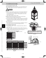
3-5. Important Note When Wiring for Y1 Type
Connect the wires referring to the diagram.
Note that the control wirings (Low Voltages) shall be
segregated from the power supply wires (High Voltage)
as follows:
1.
2.
3.
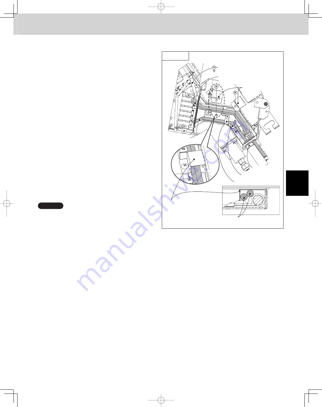
Connect the Inter-unit control wiring to U1/U2
terminals and the remote control wire to R1/R2.
Then place and fix the two clasps so that the clasps
shall cover both the remote control wires, the Inter-
unit control wiring and the 3-way wiring harness as
shown in the magnified drawing.
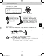
Connect the grounding conductor of the incoming
power supply to the earth (ground) screw before
connecting the power supply conductors to “L1, L2”
of the terminal block.
Securely affix the two power supply conductors (L1,
L2) in the wiring channel by the clamping strap as
shown.
NOTE
Take care not to damage the control wirings by the clasp.
Do not leave the control wirings loose.
Connection for Solenoid
Valve Kit (for 3WAY)
Y1 Type
Clamping clip
Power wiring
(field supplied)
Earth screw
Clasp
Entirely cover the control
wirings (Remote / Inter-unit
3WAY connection)
Conduit
(field supplied)
Remote control wiring
(field supplied)
Remote control wiring and Inter-unit
control wiring (field supplied)
TD831158-00̲3WAY̲VRF̲SYS.indb 31
TD831158-00̲3WAY̲VRF̲SYS.indb 31
2012/01/23 17:30:17
2012/01/23 17:30:17
Summary of Contents for U-72MF1U9
Page 118: ...Section 8 TENTATIVE ...


