


Design of 3WAY VRF SYSTEM
2
- 42
8
7
6
5
4
3
2
1
5. HOW TO PROCESS TUBING
5-3. Insulating the Refrigerant Tubing
Tubing Insulation
Thermal insulation must be applied to all unit tubing,
including the distribution joint (purchased separately).
(Fig. 2-25)
* For gas tubing, the insulation material must be heat
resistant to 248°F or above. For other tubing, it must
be heat resistant to 176°F or above.
Insulation material thickness must be 25/64 in. or
greater.
If the conditions inside the ceiling exceed DB 86°F
and RH 70%, increase the thickness of the gas
tubing insulation material by 1 step.
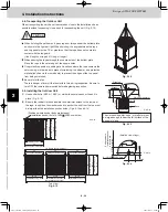
CAUTION
If the exterior of the outdoor
unit valves has been finished
with a square duct covering,
make sure you allow
sufficient space to use the
valves and to allow the
panels to be attached and
removed.
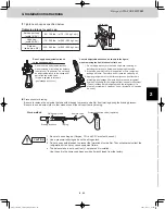
Taping the flare nuts
Wind the white insulation tape around the flare nuts at
the gas tube connections. Then cover up the tubing
connections with the flare insulator, and fill the gap at the
union with the supplied black insulation tape. Finally,
fasten the insulator at both ends with the supplied vinyl
clamps. (Fig. 2-26)
Two tubes arranged together
Liquid tubing
Gas tubing
Insulation
Three tubes arranged together
Liquid tubing
Gas tubing
Insulation
Cosmetic
(finishing) tape
Balance tubing
Four tubes arranged together
Suction tubing
Discharge tubing
Cosmetic
(finishing) tape
Balance tubing
Liquid tubing
Insulation
Fig. 2-25
Sealer (supplied)
Insulation tape (white)
(supplied)
Flare insulator (supplied)
Unit side
insulator
Flare nut
Vinyl clamps (supplied)
Tube insulator
(not supplied)
Heat resistant
248°F or above
Fig. 2-26
TD831158-00̲3WAY̲VRF̲SYS.indb 42
TD831158-00̲3WAY̲VRF̲SYS.indb 42
2012/01/23 17:30:20
2012/01/23 17:30:20
Summary of Contents for U-72MF1U9
Page 118: ...Section 8 TENTATIVE ...