


Design of 3WAY VRF SYSTEM
2
- 44
8
7
6
5
4
3
2
1
6. AIR PURGING
6. AIR PURGING
Air and moisture in the refrigerant system may have
undesirable effects as indicated below.
pressure in the system rises
operating current rises
cooling (or heating) efficiency drops
moisture in the refrigerant circuit may freeze and block
capillary tubing
water may lead to corrosion of parts in the refrigerant
system
Therefore, the indoor unit and tubing between the indoor
and outdoor unit must be leak tested and evacuated to
remove any noncondensables and moisture from the
system.
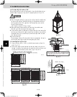
Air Purging with a Vacuum Pump (for Test Run)
Preparation
Check that each tube between the indoor and outdoor
units have been properly connected and all wiring for the
test run has been completed. Remove the valve caps
from all service ports on the outdoor unit. (Fig. 2-30) Note
that all service valves on the outdoor unit are kept closed
at this stage. The balance tube leak test is not necessary
if only 1 outdoor unit is installed.
Fig. 2-29a
Fig. 2-30
Fig. 2-29b
Manifold gauge
Outlet
Inlet
Vacuum pump
Fig. 2-31
Manifold valve
Pressure
gauge
Lo
Hi
Charge hose
Outdoor unit
Close
Open
Discharge
tube
Suction
tube
Liquid
tube
Nitrogen gas cylinder
(In vertical standing
position)
Close
Close
Open
Balance
tube
Open
Close
Open
Cylinder
valve
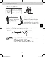
Leak test
(1) Attach a manifold valve (with pressure gauges) and
dry nitrogen gas cylinder to all service ports with
charge hoses.
The balance tube leak test is not necessary if only 1
outdoor unit is installed.
(2) Pressurize the system to no more than 512 psig
(36 kgf/cm
2
G) with dry nitrogen gas and close the
cylinder valve when the gauge reading reaches
512 psig (36 kgf/cm
2
G). Then, test for leaks with
liquid soap.
Use a manifold valve for air
purging. If it is not available,
use a stop valve for this
purpose. The “Hi” knob of
the manifold valve must
always be kept closed.
CAUTION
CAUTION
To avoid nitrogen entering the
refrigerant system in a liquid
state, the top of the cylinder
must be higher than the
bottom when you pressurize
the system. Usually, the
cylinder is used in a vertical
standing position.
Valve cap
Service port cap
Flare nut
TD831158-00̲3WAY̲VRF̲SYS.indb 44
TD831158-00̲3WAY̲VRF̲SYS.indb 44
2012/01/23 17:30:20
2012/01/23 17:30:20
Summary of Contents for U-72MF1U9
Page 118: ...Section 8 TENTATIVE ...


