


3WAY VRF SYSTEM Unit Specifi cations
4
- 12
8
7
6
5
4
3
2
1
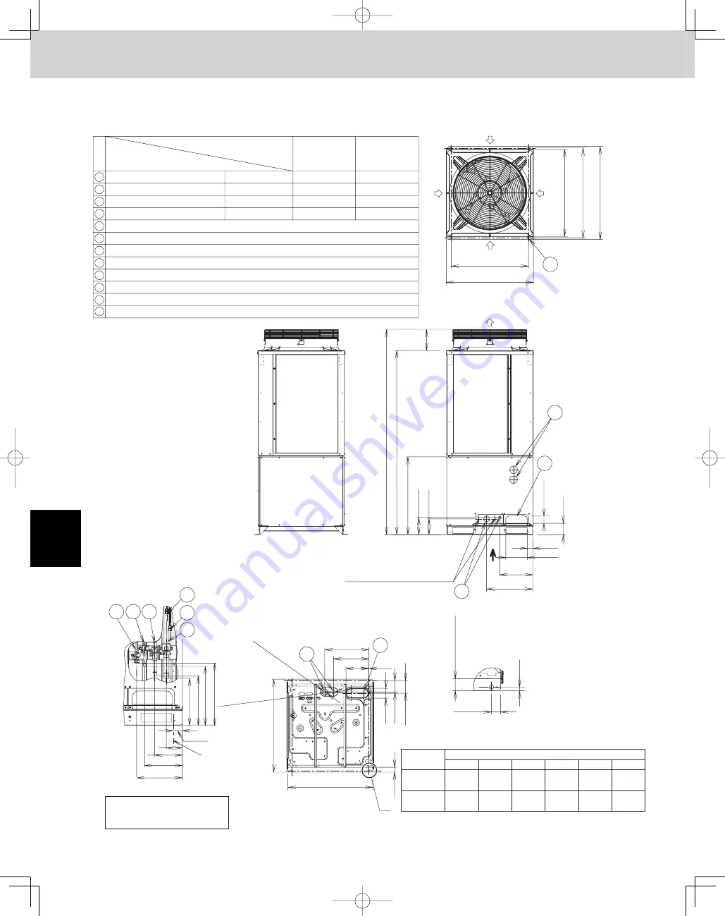
1. Outdoor Unit
U-72MF1U9, U-72MF1U9E, U-96MF1U9, U-96MF1U9E
1-3. Dimensional Data
8
5
7
12
9
6
11
12
10
9
8
7
6
5
4
3
2
1
U-72MF1U9
U-72MF1U9E
Air
intake
Air
intake
Air
discharge
Air
intake
Air
intake
Top view
Front view
Z view
Enlarged view of A
Z
A
Left side
U-96MF1U9
U-96MF1U9E
(6-Ton)
(8-Ton)
6-Ton
10-1/8
(257)
10-25/32
(274)
12-29/32
(328)
6-37/64
(167)
6-27/32
(174)
12-29/32
(328)
3-35/64
(90)
3-35/64
(90)
5-63/64
(152)
5-63/64
(152)
8-Ton
7/8" (ø22.22)
5/8" (ø15.88)
3/4" (ø19.05)
3/8" (ø9.52)
3/8" (ø9.52)
3/8" (ø9.52)
3/8" (ø9.52)
3/4" (ø19.05)
Refrigerant tube (gas tube)
brazed connection
unit : in.(mm)
unit : in.
brazed connection
brazed connection
flared connection
Refrigerant tube (discharge tube)
Refrigerant tube (liquid tube)
Refrigerant tube (balance tube)
Installation holes (4 –19/32" × 25/32" elongated holes), anchor bolts M12 or 15/32" or larger
Refrigerant port (front: knock-out hole and slit)
Refrigerant port (bottom: slit hole)
Electrical wiring port (front: ø2-23/64", ø1-7/64" knock-out holes – for conduit connection)
Electrical wiring port (bottom:ø2-23/64", ø1-1/2" knock-out holes – for conduit connection)
Pressure outlet port (for high pressure: ø5/16" (ø7.94) Schrader-type connection)
Pressure outlet port (for low pressure: ø5/16" (ø7.94) Schrader-type connection)
Knock-out hole for connecting pressure gauge (optional)
Equivalent
tonnage
Table of Measurements for Refrigerant Tube Connection
Measurements for 8-Ton assume that the supplied
connection tubing is used.
*
Size in. (mm)
a
b
c
d
e
31-1/8
(Installation hole pitch)
2-11/64
8-47/64
13-5/16
18-5/8
17-51/64
(1-33/64)
1-1/2
(Knock-out ho
le)
2-23/64
(Knoc
k-out hole)
3-15/16
34-9/64
(Bottom plate dimension)
(19/32)
Position of
installation
Position of refrigerant
connection
37-13/32
(Bottom plate dimension)
1-31/32
Installation br
ac
ket
mounting surf
ace
4-39/64
5-1/8
1-31/32
13/64
14-1/4
9-1/16
Space for creation of hole on-site
(Max. diameter
ø
1-57/64)
35
(Ceiling panel dimensions)
(8-1/2)
82-9/16
31-19/64
6-59/64
6-11/32
2-29/32
4-39/64
74-1/16
36-1/4
(Installation hole pitch)
37-1/2
(Maxim
um dimensions)
35
(Ceiling panel dimensions)
8-17/64
(210)
8-17/64
(210)
f
d
e
f
9-61/64
a
b
c
13-37/64
1
11
10
2
3
4
1-31/32
TD831158-00̲3WAY̲VRF̲SYS.indb 12
TD831158-00̲3WAY̲VRF̲SYS.indb 12
2011/12/12 17:22:43
2011/12/12 17:22:43
Summary of Contents for U-72MF1U9
Page 118: ...Section 8 TENTATIVE ...


