29
4 Mechanism
4.1.
Screen Feed Mechanism
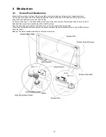
When the Motor rotates, the Gear of the Screen Main-roller is activated accordingly via the Intermediate Gears.
Two springs on the upper and lower positions adjust the Screen Film tension in the direction of the arrow so as to
bring the Screen Sub-roller into contact with the film.
As shown on the Fig.4.1.1, the Home Marker is attached on the lower position of the scrolled Screen Film so as to tell
Panaboard the screen home position required to feed the screen.
Then the Home Sensor is located on the back of the unit so as to detect the home position.
When the sensor detects the home position, the sensor will inform the control operation block in the CONTROL Board
about the status.
Based on the status, Panaboard will start or stop the screen-feed.
Summary of Contents for UB-5338C
Page 9: ...9 2 3 External View ...
Page 10: ...10 2 4 Control Panel Operation ...
Page 11: ...11 2 5 External Dimensions 2 5 1 UB 5838C ...
Page 12: ...12 2 5 2 UB 5338C ...
Page 101: ...101 13 Exploded View and Replacement Parts List ...
Page 102: ...102 13 1 Framework of Projected Diagram ...
Page 103: ...103 13 2 Cabinet Unit ...
Page 105: ...105 13 3 Motor Drive Unit Sensor Unit ...
Page 107: ...107 13 4 Control Box Unit ...
Page 109: ...109 13 5 Screen Feed Roller Unit ...
Page 111: ...111 13 6 Scanner Unit ...
Page 113: ...113 13 7 Panel Unit ...
Page 115: ...115 13 8 Frame Unit ...
Page 117: ...117 13 9 Rear Cover Unit ...
Page 119: ...119 13 10 Packing ...

