30
4.2.
Scanning Mechanism
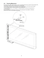
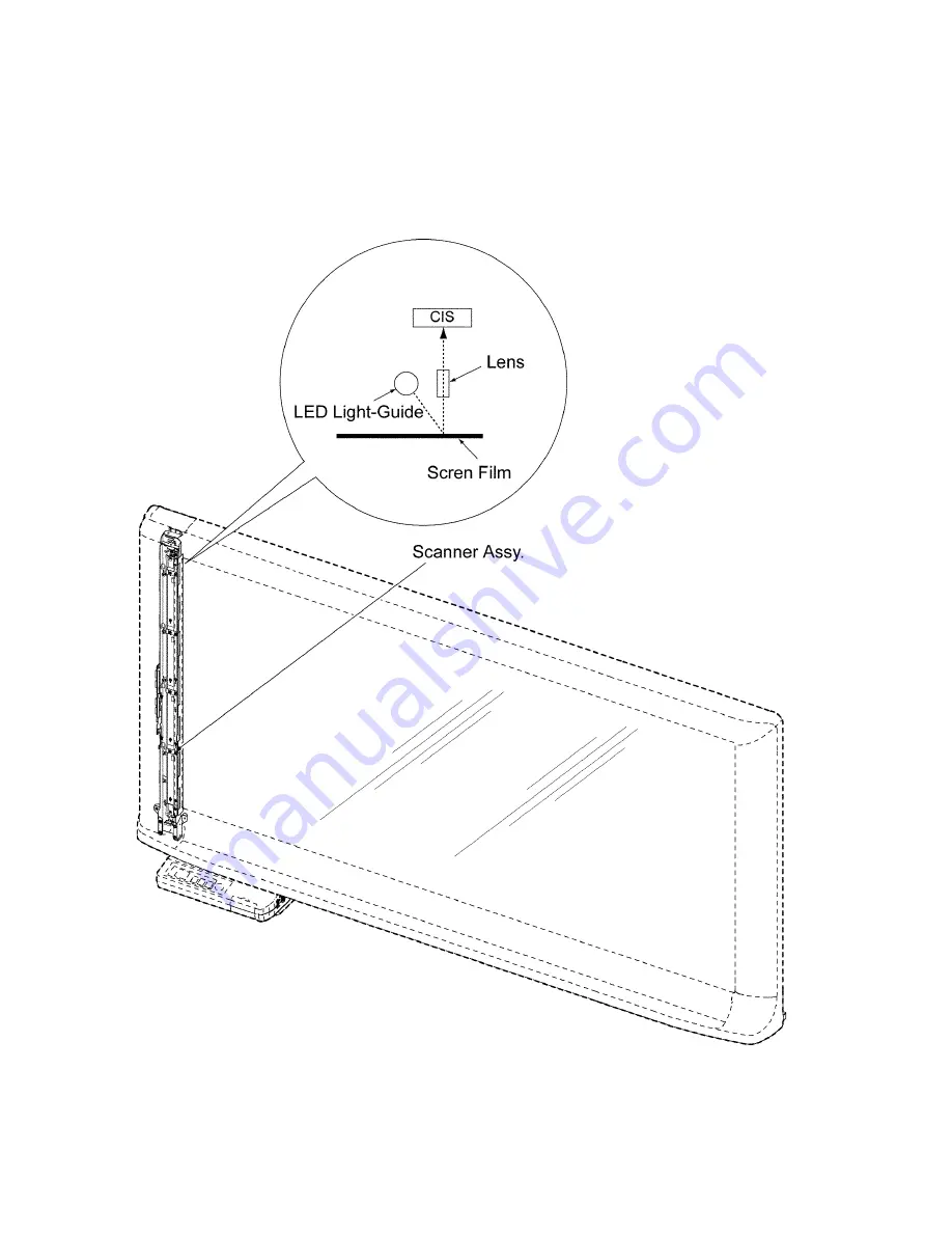
The Scanner Assy. consists of LED Light-Guide, Lens, and Contact Image Sensors so as to scan the image on the Screen Film.
A light through the LED Light-Guide is reflected from the screen film surface.
Then the reflected light will reach the Contact Image Sensors (CISs) through the Lens. The CISs will convert the light
into electrical signals, and then will transmit the signals to the SCANNER Board.
Then the SCANNER Board will convert the signals into image digital signals, and will transmit the digital signals to
the CONTROL Board.
Then the CONTROL Board will store them in its inner memories so that they can be downloaded to a USB Flash
Memory and a SD Card, or can be printed out with a printer.
Summary of Contents for UB-5338C
Page 9: ...9 2 3 External View ...
Page 10: ...10 2 4 Control Panel Operation ...
Page 11: ...11 2 5 External Dimensions 2 5 1 UB 5838C ...
Page 12: ...12 2 5 2 UB 5338C ...
Page 101: ...101 13 Exploded View and Replacement Parts List ...
Page 102: ...102 13 1 Framework of Projected Diagram ...
Page 103: ...103 13 2 Cabinet Unit ...
Page 105: ...105 13 3 Motor Drive Unit Sensor Unit ...
Page 107: ...107 13 4 Control Box Unit ...
Page 109: ...109 13 5 Screen Feed Roller Unit ...
Page 111: ...111 13 6 Scanner Unit ...
Page 113: ...113 13 7 Panel Unit ...
Page 115: ...115 13 8 Frame Unit ...
Page 117: ...117 13 9 Rear Cover Unit ...
Page 119: ...119 13 10 Packing ...

