79
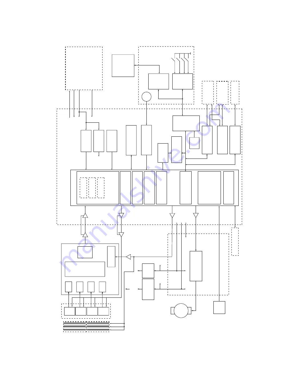
9 Block and Connection Diagrams
9.1.
Block Diagram
CIS1
CIS2
CIS3
CIS4
AGC
AGC
AGC
AGC
MUX
A/D
AFE (IC602)
RG
B
L
VDS
L
VDS
IC606
(IC607)
IC7
(IC10)
L
VDS
L
VDS
IC608
IC8
(IC605)
DC/DC
(IC603)
(IC600)
(IC604)
M
(IC6)
24V
24V
3.3V
(IC800)
3.3V
3.3V
24V
5V
SD I/F
I/O
(IC9)
Flex RISC
CPU
SOC (IC4)
Power Down
(IC14)
(IC15)
SSCG
(IC5)
256 Mbit SDRAM
(IC3)
24V
3.3V
1.8V
5V
(IC19)
LCD
(IC700,
IC701)
(IC704)
(IC16,
IC17)
OR
(IC1)
32 Mbit ROM
(IC2)
AND
(IC20)
(IC12)
(IC1
1)
(IC13)
DSP
DSP
DSP
LED
CIS
Serial IF
System Bus IF
Buffer
Scanner IF
Image Data Processing
Compression
CONTROL Board
Regulator
Reset
RTC
Buffer
USB Device
SCANNER Board
Regulator
Convertor
Reset
Motor (for Screen feed)
HOME SENSOR
Board
Motor Driver
SD Memory
Buffer
Buffer
Memory Control
USB Host
Bus Power SW
USB Memory
PC
PANEL Board
Buffer
Buffer
Battery
Power Unit
(POWER Board)
Printer
Summary of Contents for UB-5338C
Page 9: ...9 2 3 External View ...
Page 10: ...10 2 4 Control Panel Operation ...
Page 11: ...11 2 5 External Dimensions 2 5 1 UB 5838C ...
Page 12: ...12 2 5 2 UB 5338C ...
Page 101: ...101 13 Exploded View and Replacement Parts List ...
Page 102: ...102 13 1 Framework of Projected Diagram ...
Page 103: ...103 13 2 Cabinet Unit ...
Page 105: ...105 13 3 Motor Drive Unit Sensor Unit ...
Page 107: ...107 13 4 Control Box Unit ...
Page 109: ...109 13 5 Screen Feed Roller Unit ...
Page 111: ...111 13 6 Scanner Unit ...
Page 113: ...113 13 7 Panel Unit ...
Page 115: ...115 13 8 Frame Unit ...
Page 117: ...117 13 9 Rear Cover Unit ...
Page 119: ...119 13 10 Packing ...


