83
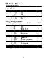
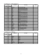
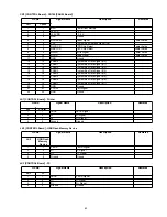
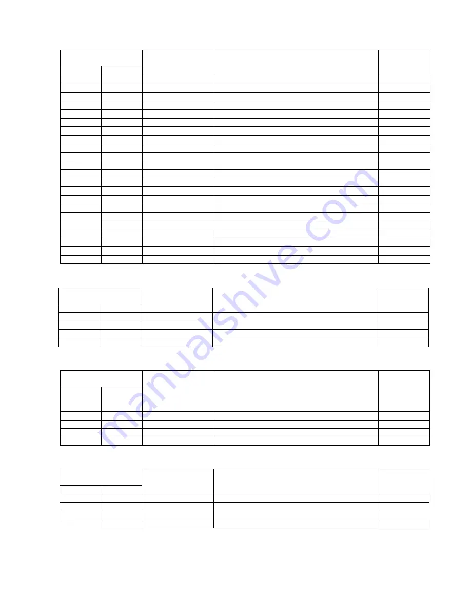
CN7 [CONTROL Board] - CN700 [PANEL Board]
Pin No.
Signal Name
Description
Remarks
CN7
CN700
1
1
BAT1
Power from Battery
2
2
+5VCC
+ 5 V
3
3
+3.3VDD
+ 3.3 V
4
4
GND
Ground
5
5
NPRESET
Reset Signal
Lower Active
6
6
PA0
System Bus Address Signal (A0)
7
7
NLCDCS
LCD Chip Select
Lower Active
8
8
NKEYCS
KEY Chip Select
Lower Active
9
9
NPWR
Write Signal
Lower Active
10
10
NPRD
Read Signal
Lower Active
11
11
GND
Ground
12
12
PSBD0
System Bus Data Signal (D0)
13
13
PSBD1
System Bus Data Signal (D1)
14
14
PSBD2
System Bus Data Signal (D2)
15
15
PSBD3
System Bus Data Signal (D3)
16
16
PSBD4
System Bus Data Signal (D4)
17
17
PSBD5
System Bus Data Signal (D5)
18
18
PSBD6
System Bus Data Signal (D6)
19
19
PSBD7
System Bus Data Signal (D7)
20
20
GND
Ground
21
21
PPORT
Port Signal
22
22
GND
Ground
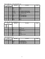
JK1 [CONTROL Board] - Printer
Pin No.
Signal Name
Description
Remarks
JK1
Printer
1
1
VBUS
VBUS Signal
2
2
D-
D- Signal
3
3
D+
D+ Signal
4
4
Ground
Ground
JK2 [CONTROL Board] - USB Flash Memory Device
Pin No.
Signal Name
Description
Remarks
JK2
USB Flash
Memory
Device
1
1
VBUS
VBUS Signal
2
2
D-
D- Signal
3
3
D+
D+ Signal
4
4
Ground
Ground
JK3 [CONTROL Board] - PC
Pin No.
Signal Name
Description
Remarks
JK3
PC
1
1
VBUS
VBUS Signal
2
2
D-
D- Signal
3
3
D+
D+ Signal
4
4
Ground
Ground
Summary of Contents for UB-5338C
Page 9: ...9 2 3 External View ...
Page 10: ...10 2 4 Control Panel Operation ...
Page 11: ...11 2 5 External Dimensions 2 5 1 UB 5838C ...
Page 12: ...12 2 5 2 UB 5338C ...
Page 101: ...101 13 Exploded View and Replacement Parts List ...
Page 102: ...102 13 1 Framework of Projected Diagram ...
Page 103: ...103 13 2 Cabinet Unit ...
Page 105: ...105 13 3 Motor Drive Unit Sensor Unit ...
Page 107: ...107 13 4 Control Box Unit ...
Page 109: ...109 13 5 Screen Feed Roller Unit ...
Page 111: ...111 13 6 Scanner Unit ...
Page 113: ...113 13 7 Panel Unit ...
Page 115: ...115 13 8 Frame Unit ...
Page 117: ...117 13 9 Rear Cover Unit ...
Page 119: ...119 13 10 Packing ...


