background image

14

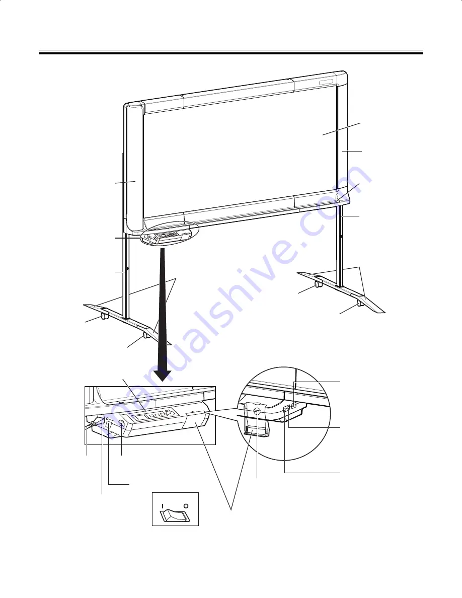
Part Names and Functions

OFF

ON

Screen Film

Frame

Tray

Stand

Caster

Caster

with Lock

Scanner

Control Box

Stand

Control Panel

Power Cord

Battery Holder

AC Inlet

Power Switch

SD Memory Card Cover

SD Memory 
Card Slot

USB Connector-A 
for USB Flash 
Memory Device

Caster with Lock

Caster

USB Connector-B 
for Computer

USB Connector-A 
for Printer

Fall-prevention
Extension Leg

Fall-prevention 
Extension Leg

UB5838C-PJQXC0259ZA_mst.book  14 ページ  2009年5月26日 火曜日 午後2時59分

Summary of Contents for UB-5338C

Page 1: ...the Installation manual on page 38 through 55 Before operating this unit please read these instructions completely and keep them carefully for future reference This unit is designed for installation b...

Page 2: ...e is adversely effected by operational errors static electricity electrical noise vibration dust or when the power has been cut off due to malfunction repair or inadvertently the memory contents may b...

Page 3: ...erates uses and can radiate radio frequency energy and if not installed and used in accordance with the instruction manual may cause harmful interference to radio communications Operation of this equi...

Page 4: ...rency Bank notes and checks Bank and government bonds and securities Passports licenses official or private documents identification cards and the like Copyright materials or trademarks without the co...

Page 5: ...dentJPEG Group This software is based on the libtiff which has the following copyrights Copyright C 1988 1997 Sam Leffler Copyright C 1991 1997 Silicon Graphics Inc The information given in this Opera...

Page 6: ...ported Not all SD memory cards are compatible with this unit Printing with an External Printer Allows scanned hand written text diagrams to be printed with an external printer via USB cable Computer I...

Page 7: ...omputer 21 Moving the Electronic Board 23 Setting the Unit 24 Setting the number of copies 24 Setting for scanning time display 24 File format set up 25 Setting for Full Size Scanning UB 5838C only 26...

Page 8: ...rating the unit or plug may emit smoke or become hot to the touch When you operate this product the power outlet should be near the product and easily accessible To ensure safe operation the power co...

Page 9: ...ments or water gets into the unit turn the unit off and unplug the unit immediately Contact your dealer for service Operating the contaminated unit can cause fire or electric shock Never open or remov...

Page 10: ...cord attached it can cause damage to the cord which could result in fire or electric shock Do not install the unit except by a qualified service personnel CAUTION After installing or moving the unit l...

Page 11: ...IS INSERTED INTO ANY 13 AMP SOCKET If a new plug is to be fitted please observe the wiring code as shown below If in any doubt please consult a qualified electrician WARNING This appliance must be ea...

Page 12: ...esult in damage to the unit Do not attach chart paper to the screen film for copying as this may result in damage to the unit Markers and Eraser Use only the included or designated markers and eraser...

Page 13: ...g the memory device to another person Using basic operations such as format or delete on a computer may not completely erase the data from the memory device To guarantee that the data you wish to eras...

Page 14: ...ol Box Stand Control Panel Power Cord Battery Holder AC Inlet Power Switch SD Memory Card Cover SD Memory Card Slot USB Connector A for USB Flash Memory Device Caster with Lock Caster USB Connector B...

Page 15: ...mode will be indicated next to the icons on the left side of the display Color For scanning color images B W For scanning black and white images Preview mode Set up mode Returns to the previous screen...

Page 16: ...Key or the Advance Key and enter the 4 digit password Note Do not forget the Password If you forget the Password call your dealer Screen Erase Announce function After scanning the screen the followin...

Page 17: ...e an SD memory card or a computer the following file formats can be selected refer to File format set up on page 25 Color PDF JPEG format B W PDF JPEG format Images output to a USB flash memory device...

Page 18: ...ning has finished a preview of the scanned image is shown on the display Note Do not remove the USB flash memory device until the preview is shown on the display 5 Press the Advance Key to zoom in on...

Page 19: ...riate formatting software You can also download the formatting software for the SD memory card from the following site http panasonic jp support global cs sd download sd_formatter html 3 Press the Mod...

Page 20: ...nformation on saving files on an SD memory card refer to page 17 1 Set the power switch to on I 2 Turn the external printer on and load the paper 3 Connect the external printer to USB Connector A for...

Page 21: ...functions with Full Speed USB 2 0 This unit will not run at the rated speed of Hi Speed USB 2 0 2 Microsoft Windows 2000 operating system hereafter Windows 2000 3 Microsoft Windows XP operating system...

Page 22: ...ned with the electronic board the first image file will be deleted The scanned image files will be deleted if the USB cable is removed 7 Press the Advance Key to zoom in on the image with the electron...

Page 23: ...d to the unit If so disconnect them 2 Release the lock A and fold back the fall prevention extension legs B as follows 3 Release the caster locks and move the unit Note Always move the unit with 2 peo...

Page 24: ...epeatedly to select the desired number of copies 3 Press the Mode Key to return to standby mode Note Scanning can be started immediately by pressing the Start Stop Key instead of the Mode Key It is po...

Page 25: ...ter 1 Press the Set up Key The set up screen is displayed 2 Press the Set up Key repeatedly to select the following item 3 Press the Advance Key repeatedly to select PDF or JPEG When PDF is selected a...

Page 26: ...Set up Key The set up screen is displayed 2 Press the Set up Key repeatedly to select the following item 3 Press the Advance Key The time set up screen is displayed Select the desired setting you wish...

Page 27: ...e the password settings If the password setting has been set to off the unit will return to standby mode If the password setting is set to on proceed to perform the following operations 7 Press the Ad...

Page 28: ...up Key The set up screen is displayed 2 Press the Set up Key repeatedly to select the following item If this item is not displayed the unit does not recognize the printer Make sure that the printer i...

Page 29: ...sives or surfactants as this may result in discoloration or difficulty of erasing Do not wipe the screen film with a dry cloth as this may generate a static charge When the erasing surface of the eras...

Page 30: ...holder with the battery side upward and retighten the screw in step 1 4 Set the current time See page 26 Note Dispose of expired battery quickly by covering the terminals in tape and following the dis...

Page 31: ...r blurred The writing on the screen is too thin or light Make thicker darker lines or use a new marker Black or white lines appear on the scanned image or the scanned image is dark or blank The unit i...

Page 32: ...USB flash memory device has not been used since it was formatted using FAT32 Once a file has been written subsequent operations will be performed much more quickly When images are saved they are rota...

Page 33: ...printer manual U308001 Unsupported printer is connected Connect compatible printer 37 U408001 The USB cable connecting the printer and the unit was removed while copying Connect the USB cable for prin...

Page 34: ...B flash memory device are set to read only for UB 5838C UB 5838C for UB 5338C UB 5338C Change folder property to writable using a computer 17 U306014 U306160 U406035 The following folders for storing...

Page 35: ...g software You can also download the formatting software for the SD memory card from the following site http panasonic jp support global cs sd download sd_formatter html U413209 The USB cable connecti...

Page 36: ...F Humidity 15 80 RH Display 1 8 Color LCD Battery for Clock Lithium Coin Battery CR2032 1 PC interface Full Speed USB 2 0 This unit does not function with Hi Speed USB 2 0 Input Block Panel surfaces 2...

Page 37: ...sd download sd_formatter html To purchase separately available items contact your dealer Model No UB 5838C UB 5338C Printer Output Block Interface Full Speed USB 2 0 Support printer language PCL 3 GU...

Page 38: ...es and Installation Procedures 51 Optional Stand Assembly UE 608035 53 Included Parts 53 Assembly Instructions 54 Request assembly of the Electronic Board stand and wall mounting from your dealer Befo...

Page 39: ...use electric shock or injury Be sure to use the specified parts for the installation Otherwise it may cause fire electric shock or injury Notes in the operating instructions or notes of labels on the...

Page 40: ...accessories to the users 1 Markers Black Red Blue 1 each 2 Eraser 1 3 USB cable 1 4 Operating Instructions 1 5 Warranty card U S A models only 1 No Part Name Illustration Q ty Remarks Washer 4 For as...

Page 41: ...he upper and lower sides of the center of the unit Note When handling the screen unit grasp the side cover on either side of screen Do not grasp the screen film surface as this may scratch it When rem...

Page 42: ...ntact may damage the screen film When using the stand advance to step 10 Wall mounting 5 Remove the four rivets Note To remove the rivets turn them counterclockwise with a screwdriver The fixed part o...

Page 43: ...ional stand to the unit Each stands has four holes A B C D 1 Attach the stand to the unit with the locking caster up 2 When attaching the unit to the stand at normal height 1 830 mm 6 2 32 tighten the...

Page 44: ...ts included in the stand to the holes in the stand that are not already in use normal height 2 places higher than normal height 4 places 13 Attach the clamp to the stand Attach the 3 clamp for the pow...

Page 45: ...the AC inlet of the control box 3 Remove the battery protection sheet Setting the time Set the time as follows 1 Turn the power switch on The time set up screen is displayed automatically when the pow...

Page 46: ...mory card installed is shown on the display Normal operation If not Contact the store or dealer from which the unit was purchased 4 Use the accessory marker to draw a large across the entire scannable...

Page 47: ...rough 13 on pages 41 44 in reverse to repack the unit and accessories Use the joints to fasten the shipping box Note When handling the screen unit grasp the side cover on either side of screen Do not...

Page 48: ...s can cause heat smoke or fire 1 Necessary Tools and Parts not included with the product Drill Screwdriver Measuring tape Level 8 screws M6 size 2 Before Starting 1 Make sure that the wall is strong e...

Page 49: ...for UB 5838C and UB 5338C Make sure that the position of the holes are level and perpendicular to each other i e the unit will not be crooked The lateral tolerance of the hole position of the wall mo...

Page 50: ...ws with a size of M6 appropriate for your type of wall Tighten the wall mounting hardware so that it will not become loose When drilling the holes and installing the wall mounting fixtures follow the...

Page 51: ...ds may be necessary depending on the wall Metal or Concrete walls Stud plugs sold in stores are needed Drill eight holes in the wall For the correct hole size refer to the instructions for the particu...

Page 52: ...articular split wing toggles used After the arms expand pull the wall mounting fixture out until the arms of the split wing toggle grip firmly into the wall Tighten the bolt until the wall mounting fi...

Page 53: ...ing the screws so keep it in a safe location Note Before assembly be sure to lock the casters No Part name Illustration Q ty Stand Base 2 Support Beam 2 Fall prevention Extension Leg 4 Flat Head Screw...

Page 54: ...Optional Stand Assembly UE 608035 54 Assembly Instructions 1 Assemble the fall prevention extension legs 2 Assembling the stand Locking casters side rear...

Page 55: ...E 608035 55 Installation 3 Pull the fall prevention extension legs down Note When folding back the fall prevention extension legs release the lock as follows 1 2 4 Mount the unit Refer to Assembling t...

Page 56: ...f you wish to discard electrical and electronic equipment please contact your dealer or supplier for further information Information on Disposal in other Countries outside the European Union These sym...

Reviews: