29
6 SCREEN OPERATION
6.1.
Position Detection Mechanism
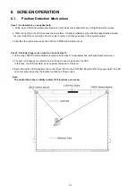
Case 1: No obstacle is on an optical path
1. LEDs, which CMOS Camera Module (located on both sides of screenboard) has, emit light toward the screen.
2. When the light from the LEDs reaches the board fame, the light is reflected by the reflection tape attached around
the inner side of the covers (Side Covers, Lower Covers), and then goes back to the original position.
3. After that, the light is scanned by the CCD that CMOS Camera Module has.
Case 2: Obstacle (finger or pen top) is on an optical path
1. LEDs, which CMOS Camera Module (located on both sides of screenboard) has, emit light toward the screen.
2. The light is blocked by an obstacle, and so the light does not go back to the CCD .
In this case, the CCD waveform has any partial depression of the level.
3. By monitoring the CCD waveform, the control block (CPU on the CONTROL Board) will find the angle which the CCD
can not scanned to specify the location touched by a finger or pen.
Note:
The control block has an ability to detect 100 locations per second.
Summary of Contents for UB-T580
Page 11: ...11 3 COMPONENT IDENTIFICATION 3 1 Main Unit ...
Page 12: ...12 3 2 Stylus Pen ...
Page 17: ...17 4 5 Unpacking the elite Panaboard from Its Packaging ...
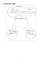
Page 28: ...28 5 SECTIONAL VIEW ...
Page 48: ...48 12 CIRCUIT BOARDS Index 12 1 RELAY Board 12 2 LED Board ...
Page 50: ...50 13 PARTS LOCATION AND MECHANICAL PARTS LIST ...
Page 53: ...53 13 1 2 For UB T580W To be continued later ...
Page 56: ...56 13 2 2 For UB T580W To be continued later ...
Page 57: ...57 14 REPLACEMENT PARTS LIST ...

