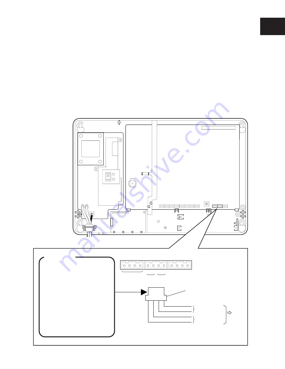
INSTALLATION OF CCU
I-9
CCU
Exchange line connector CN1
A B
2
A B
1
1 2 3 4
A B A B
DDK connector
Exchange line 1
Exchange line 2
Exchange line
To
NTTP
or PBX
Not used
■
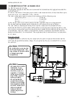
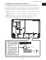
CONNECTION OF EXCHANGE LINE / PBX LINES
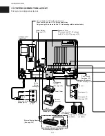
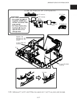
Two Exchange lines or PBX lines can be connected to the 416 system at initial mounting.
NOTE : Installing the optional expansion card allows up to four lines to be connected to the 416 system. (See page I-20.)
The Exchange lines or PBX lines can be connected directly to the CCU using a DDK connector. A
single DDK (4-terminal) connector allows two Exchange lines or PBX lines to be connected.
q
Connect Exchange line 1 “A” to pin No.3 on the DDK connector, and Exchange line 1 “B” to
pin No.4.
w
Connect Exchange line 2 “A” to pin No.1 on the DDK connector, and Exchange line 2 “B” to
pin No.2.
e
Connect to Exchange line connector (Exchange line 1 / Exchange line 2) on the CCU.
r
In the same way, connect Exchange lines 3 and 4 on the expansion card.
WARNING
• Use a plier for tightening
wires to DDK connectors
to prevent from loose
wiring.
• Do not bundle exchange
lines and AC power line
or internal lines together
outside the CCU. Dis-
tance of 50cm is required
between them to assure
proper functioning.
NOTE : In this manual “T” and “R” on the PCB have been replaced with “A” and “B”, respectively, in the description.

