INSTALLATION OF CCU
I-13
CCU
PF TEL 1
1 2 3 4
A B
A
B
A
B
A B
DDK connector
SLT (LD type)
SLT (DTMF type)
or
To telephone
Socket
6
1
Master
Socket (LJU)
1
2
3
6
5
4
2(B)
5(A)
To Exchange line Circuit
Exchange
line 1
PF TEL
1
PF TEL 1
■
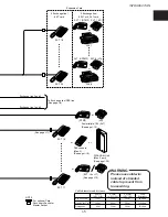
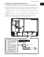
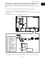
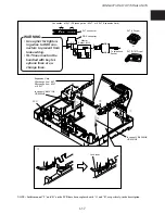
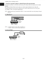
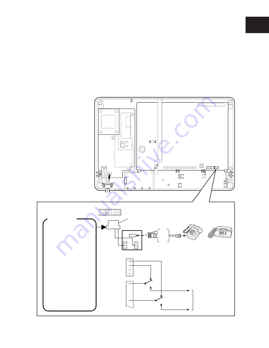
CONNECTION OF SINGLE LINE TELEPHONE (SLT) FOR POWER FAILURE
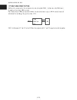
Connect the Single Line Telephone for use in power failures to the PF1 port of the CCU.
During a power failure, the SLT connected to the PF1 port will be directly connected to Exchange
Line 1.
NOTE : A SLT connected to PF1 of the CCU is for power failures and cannot be used for other purposes.
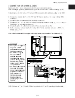
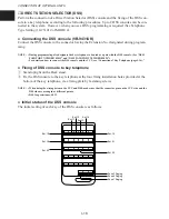
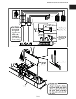
q
Connect “A” to pin No.3 of the DDK connector and “B” to pin No.4.
w
Connect “A” and “B” lines from the DDK connector to the “5” and “2” terminals of the Master
Socket (LJU).
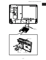
e
Connect SLT to the modular jack of the Master Socket (LJU).
NOTE : In this manual “T” and “R” on the PCB have been replaced with “A” and “B”, respectively, in the description.
WARNING
• Use a plier for
tightening wires
to DDK connec-
tors to prevent
from loose
wiring.
• SLT lines must
not be bundled
with key tel-
ephone lines or
exchange lines
outside the CCU.
• PF2 is not avail-
able.

