CONNECTION OF OPTIONAL UNITS
I-18
■
DIRECT STATION SELECTOR (DSS)
Perform the connection of a Direct Station Selector (DSS) console and the fixing of the DSS con-
sole to a key telephone, according to the following procedures. Up to 2 DSS consoles can be con-
nected to the system. However, when you use a DSS, programming is required (See Telephone
Type Setting (10-25) 01# of MODE 4).
●
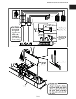
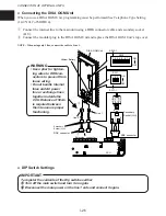
Connecting the DSS console (VB-9431UK)
Connect the DSS console to the connector having the Extension No. designated during program-
ming.
NOTE : • During programming, also designate the key telephone to be used as a pair with the DSS console. (See “DSS1
PAIR PORT NUMBER 0901#” and “DSS2 PAIR PORT NUMBER 0902#”.)
• For details on how to connect the DSS console and the CCU, see “Connection of Key Telephone (page I-16).”
●
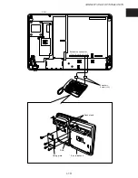
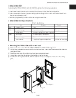
Fixing of DSS console to key telephone
q
Stand upright on the Desk stand.
w
Fix the DSS console to the key telephone at the four fixing installation holes provided at the
bottom of the key telephone, via a fixing plate by fastening screws.
NOTE : • When doing the wiring between the CCU and DSS, make sure that the connector pins on the CCU side and the
DSS side are arranged at different points.
• DSS loop resistance: 40
Ω
.
●
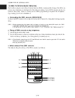
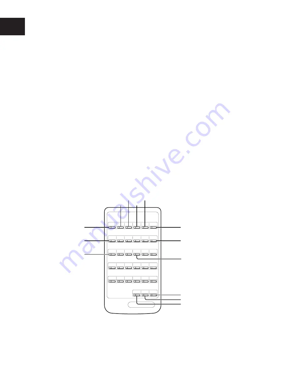
Initial status of the DSS console
The initial setting of each key of the DSS console is as follows.
Ext.10
Ext.16
Ext.22
Zone 3 Paging
Zone 2 Paging
Zone 1 Paging
Ext.15
Ext.21
Ext.11
Ext.12
Ext.13
Ext.14
Ext.25

