CONNECTION OF OPTIONAL UNITS
I-20
■
CALL LOGGING I/F CARD
Installing the Call Logging I/F Card (VB-9283UK) to the CCU enables the following operations.
(1) Connection of a printer outputs a record of calls (Call Logging).
(2) Connection of a Personal Computer enables programming by a Personal Computer.
NOTE : The necessary communications software must be installed when using the Personal Computer.
●
Call Logging
I/F Card Specifications
Table 3. Specifications
Item
Description
Interface
I/F
RS-232C x 1
Output signals
1pin: FG, 2pin: TXD, 3pin: RXD, 5pin: CTS, 6pin: DSR, 7pin: SG, 8pin: DCD, 20pin: DTR
Protocol
Communication channel
Asynchronous, full duplex
Baud rate
1200/4800
Parity
EVEN/ODD/NONE
Bit lengths
Start bit
1 bit
Data bit
7/8 bit
Stop bit
1/2 bit
MODEM
Baud rate
300 Baud
Mode
Full duplex, asynchronous, FSK
Standard
CCITT
Others
Power supply
12V and 5V Supplied from CCU
Current consumption
4mA
●
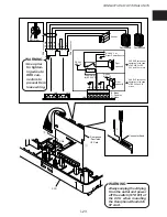
Installing the
Call Logging
I/F Card
WARNING
Always unplug the AC plug from the outlet and power off the switch (STD BY) of the CCU
when mounting the Call Logging I/F card.
q
Make holes at A, B, C shown on the figure using pliers.
w
Align the protrusion on the CCU with the hole on the Call Logging I/F Card-A board, and
secure by screw
w
.
e
Align the Call Logging I/F Card-B board with the installation groove on the CCU, and insert
until the Call Logging I/F Card-B board is locked by the claws on the CCU.
r
Insert the connector from the Call Logging I/F Card-A board into CN5 on the CCU.
t
Attach the EMI filter to the cable.
y
Put the cables together into the cable clamp.
●
Connecting the Printer (Serial Printer)
q
Connect the printer via the RS-232C cable referring to the specifications of Table 3 and Figure.
NOTE : For details on the output format of the call record, see programming MODE8 “Communication Parameter Setting”.
●
Connecting the Personal Computer
q
Connect the Personal Computer via the RS-232C cable referring to the specifications of Table 3
and Figure.

