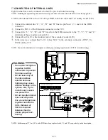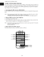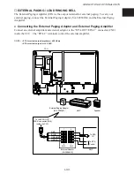
CONNECTION OF OPTIONAL UNITS
I-21
1
13
14
25
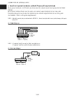
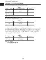
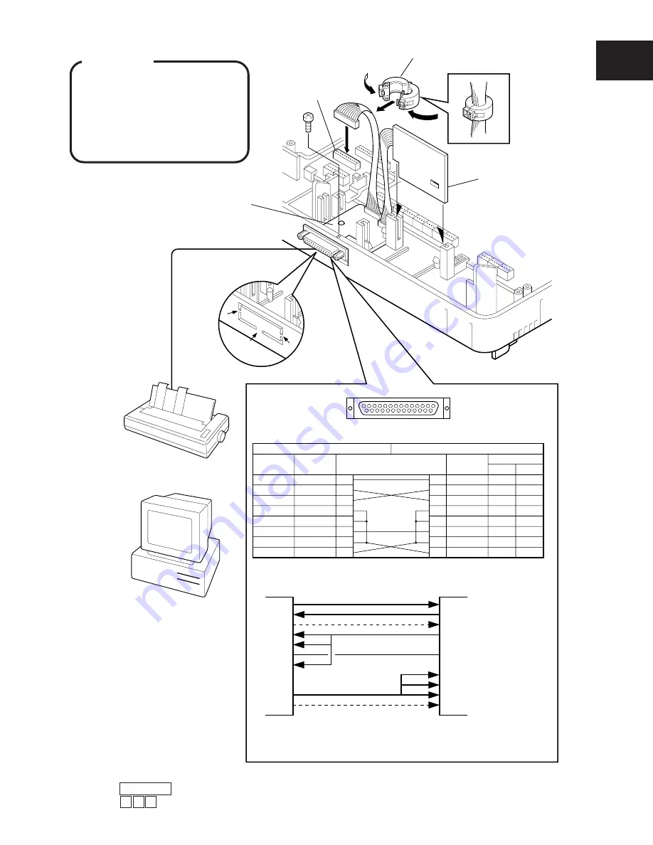
Call Logging RS-232C
Circuit
type(EIA)
Signal
name
AA
BA
BB
CB
CC
AB
CD
DTR
SG
DSR
CTS
RXD
TXD
FG
1
2
3
5
6
20
CF
DCD
8
7
Pin No. and connection
Signal
name
Circuit type
EIA
CCITT
AA
BA
BB
CB
CC
AB
CF
DCD
SG
DSR
CTS
RXD
TXD
FG
1
2
3
5
6
8
7
101
103
104
105
106
102
109
CD
DTR
20
108.2
Printer or Personal Computer RS-232C
or
Personal
Computer
Serial
Printer
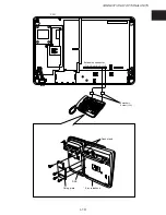
RS-232C Cable
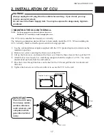
Call Logging I/F
Card-A board
Call Logging
I/F Card-B board
CCU
CN5
q
e
r
w
●
RS-232C to RS-232C
●
If Connecting direct RS-232C to 9Pin (DB9) Interface
2
3
4
5
6
7
8
20
22
2
3
7
4
5
1
6
8
9
Personal
Computer
Recevive Data
Transmit Data
Request To Send
Data Terminal Ready
Signal Ground
Carrier Detect
Data Set Ready
Clear To Send
Ring Indicator
A
B
C
EMI Filter
t
Call Logging I/F
Note : Dotted lines need not be connected when wiring.
RS-232C
DB 9
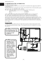
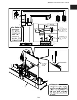
WARNING
Always unplug the AC plug
from the outlet and power off
the switch (STD BY) of the
CCU when mounting the Call
Logging I/F card.
●
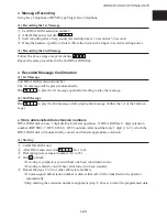
To Start to Print or Display Information
q
Press ON/OFF key.
w
Press # 9 3 .

