116
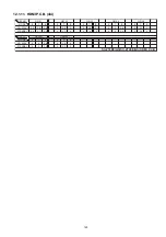
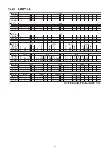
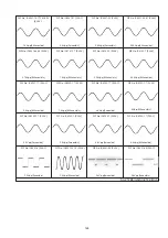
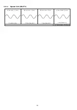
12 Voltage Measurement & Waveform Chart
Note:
• Indicated voltage values are the standard values for the unit measured by the DC electronic circuit tester (high-impedance) with
the chassis taken as standard.
Therefore, there may exist some errors in the voltage values, depending on the internal impedance of the DC circuit tester.
• Circuit voltage and waveform described herein shall be regarded as reference information when probing defect point because it
may differ from actual measuring value due to difference of Measuring instrument and its measuring condition and product itself.
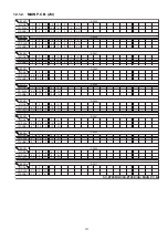
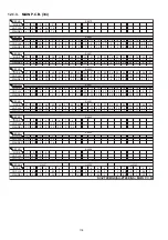
12.1. Main Unit (SU-ZT2)
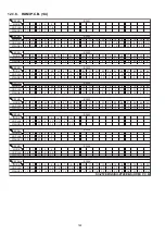
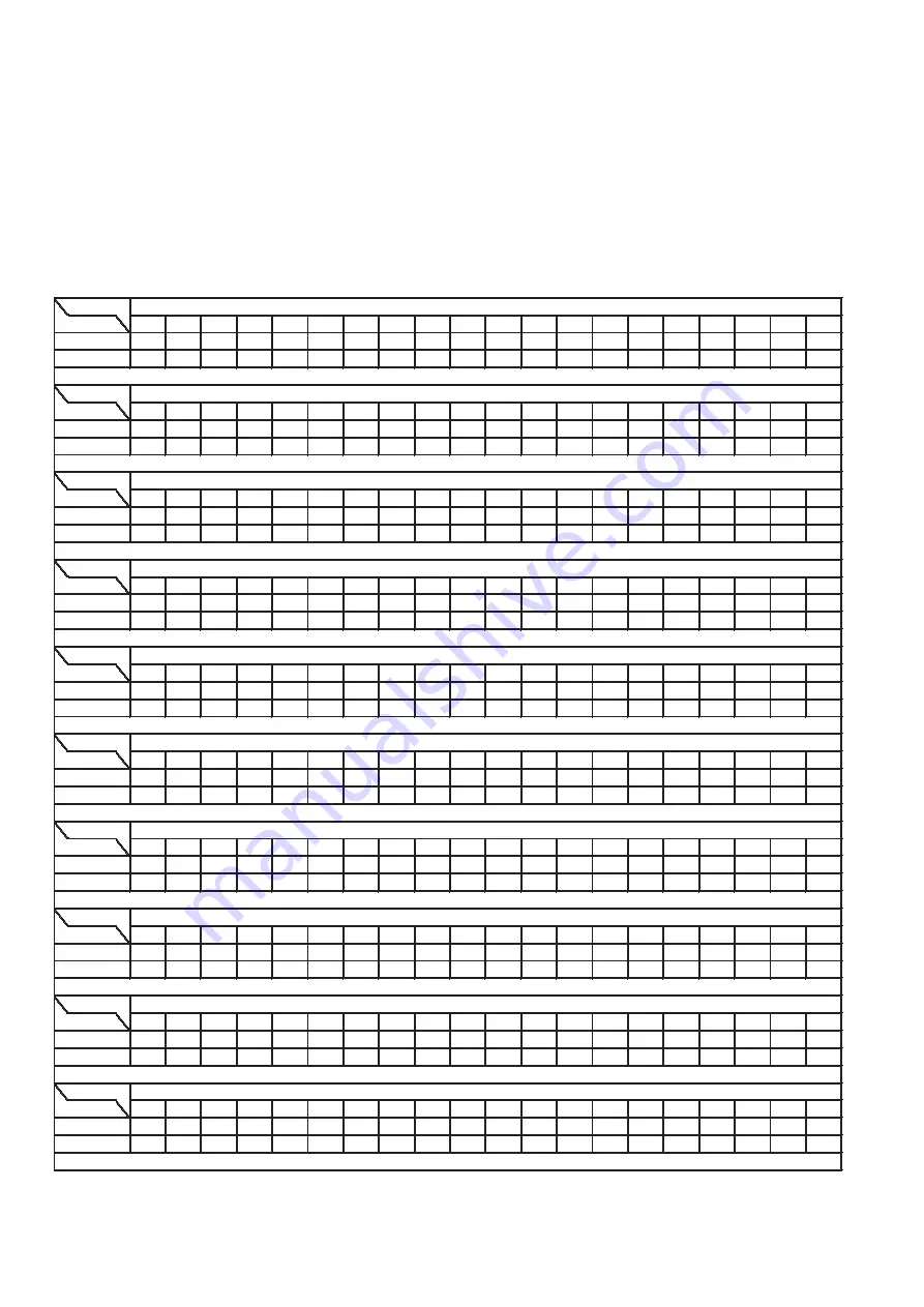
12.1.1. MAIN P.C.B. (1/4)
REF NO.
MODE
1
2
3
4
5
6
7
8
9
10
11
12
13
14
15
16
17
18
19
20
CD PLAY
0
0
0
0
0
0
0
0
0
0
0
-6.9
0
0
0
0
0
0
0
0
STANDBY
0
0
0
0
0
0
0
0
0
0
0
-6.9
0
0
0
0
0
0
0
0
REF NO.
MODE
21
22
23
24
25
26
27
28
29
30
31
32
33
34
35
36
37
38
39
40
CD PLAY
0
0
0
0
0
3.3
6.9
0
0
0
0
0
0
0
0
0.1
0
0
0
0
STANDBY
0
0
0
0
0
3.3
6.9
0
0
0
0
0
0
0
0
0.1
0
0
0
0
REF NO.
MODE
41
42
43
44
45
46
47
48
49
50
51
52
53
54
55
56
CD PLAY
0
0
0
0
0
0
0
0
0
0
0
0
0
0
0
0
STANDBY
0
0
0
0
0
0
0
0
0
0
0
0
0
0
0
0
REF NO.
MODE
1
2
3
4
5
6
7
8
CD PLAY
0
0
0
0
0
0
0
5.0
STANDBY
0
0
0
0
0
0
0
5.0
REF NO.
MODE
1
2
3
4
5
6
7
8
CD PLAY
0
0
0
0
0
0
0
5.0
STANDBY
0
0
0
0
0
0
0
5.0
REF NO.
MODE
1
2
3
4
5
6
7
8
CD PLAY
0
0
0
-6.9
0
0
0
6.9
STANDBY
0
0
0
-6.9
0
0
0
6.9
REF NO.
MODE
1
2
3
4
5
6
7
8
CD PLAY
0
0
0
-6.9
0
0
0
6.9
STANDBY
0
0
0
-6.9
0
0
0
6.9
REF NO.
MODE
1
2
3
4
5
6
7
8
CD PLAY
0
0
0
-6.9
0
0
0
6.9
STANDBY
0
0
0
-6.9
0
0
0
6.9
REF NO.
MODE
1
2
3
4
5
6
7
8
CD PLAY
0
0
0
-6.9
0
0
0
6.9
STANDBY
0
0
0
-6.9
0
0
0
6.9
REF NO.
MODE
1
2
3
4
5
6
7
8
CD PLAY
0
0
0
-6.9
0
0
0
6.9
STANDBY
0
0
0
-6.9
0
0
0
6.9
IC4202
IC4203
IC4302
SC-ZT2EE/GS(SU-ZT2EE/GS) MAIN P.C.B.
IC4301
IC4102
IC4201
IC4001
IC4001
IC4001
IC4101
Summary of Contents for VIERA Link SB-ZT2EE
Page 10: ...10 5 Location of Controls and Components 5 1 Main Unit SU ZT2 ...
Page 11: ...11 5 2 Speaker Unit SB ZT2 5 3 Remote Control ...
Page 12: ...12 6 Installation ...
Page 13: ...13 6 1 Basic Connections 6 1 1 Connecting equipment with HDMI terminal TV DVD recorder etc ...
Page 14: ...14 6 1 2 Connecting equipment without HDMI terminal DVD player VCR etc ...
Page 15: ...15 6 1 3 Connecting STB etc and audio terminals DVD player etc ...
Page 16: ...16 6 1 4 Other connections ...
Page 17: ...17 6 2 AC power supply connection ...
Page 18: ...18 7 Speaker setting SB ZT2 7 1 Setting the speakers Front and Surround speakers ...
Page 19: ...19 ...
Page 20: ...20 7 2 Setting surround speakers ...
Page 28: ...28 9 2 2 Speaker Unit SB ZT2 ...
Page 29: ...29 9 2 3 Speaker Unit SB ZT2 Wireless Link ...
Page 30: ...30 ...
Page 32: ...32 ...
Page 33: ...33 10 1 Main Parts Location Diagram 10 1 1 Main Unit SU ZT2 ...
Page 34: ...34 10 1 2 Speaker Unit SB ZT2 ...
Page 36: ...36 10 2 2 Speaker Unit SB ZT2 ...
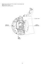
Page 49: ...49 Step 4 Remove the Weight ...
Page 50: ...50 Step 5 Remove 10 screws ...
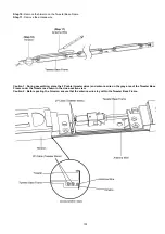
Page 54: ...54 Step 11 Remove 2 screws Step 12 Lift up to remove Arm Cover A ...
Page 56: ...56 Step 14 Tilt the Woofer Block in order as arrows shown to detach it from the Tweeter Block ...
Page 67: ...67 Step 3 Remove the heatsink with the IC5701 ...
Page 68: ...68 Step 4 Remove 1 screw Step 5 Remove IC5701 from the heatsink ...
Page 70: ...70 Step 4 Place the heatsink with the IC5701 onto the SMPS P C B ...
Page 82: ...82 Step 4 Remove 3 screws Step 5 Remove the Power Button ...
Page 87: ...87 Step 3 Remove 4 screws Step 4 Lift up to remove Woofer Speaker SP1 ...
Page 111: ...111 Step 11 Remove 3 screws ...
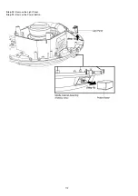
Page 112: ...112 Step 12 Remove the Light Panel Step 13 Remove the Power Button ...
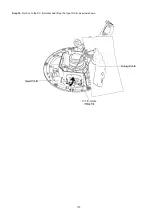
Page 113: ...113 Step 14 Hold on to the P C B Holder and lift up the Input P C B as arrow shown ...
Page 114: ...114 Step 15 Place the D Amp P C B and Input P C B on an insulation sheet ...
Page 132: ...132 ...
Page 133: ...133 14 Overall Simplified Block 14 1 Signal Flow SU ZT2 ...
Page 144: ...144 ...
Page 148: ...148 ...
Page 168: ...168 ...
Page 176: ...176 ...
Page 178: ...178 ...
Page 182: ...182 ...


