137
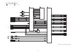
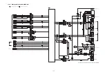
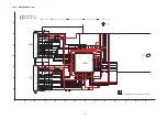
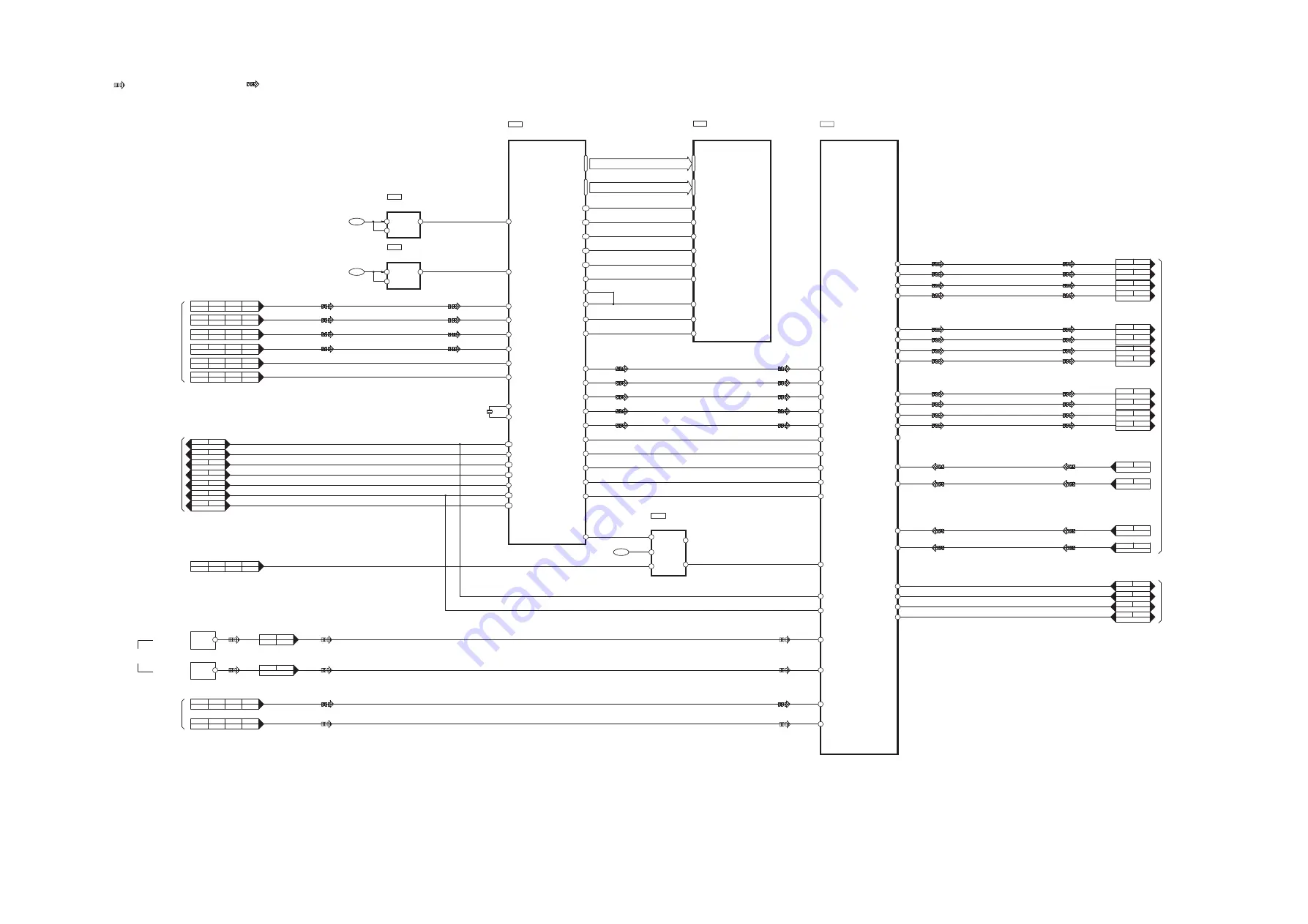
15.1.4. DSP BLOCK DIAGRAM
DSP
C2HBCY000030
51
DAO DATA0
57
SD DQM0
79
SD DQM1
82
SD CLKEN
81
SD CLKIN
49
DAO DATA1
48
DAO DATA2
IC1000
18 XTO
17 XTI
16
XTAL OUT
X1000
4
SCP1 IRQ#
6
SCP1 CS
DAI DATA0
27
VDDA(3.3V)
21
VDD1
42
DAI DATA1
DAI DATA2
DAI DATA3
26
24
23
29 DAI SCLK1
30 DAI LRCLK1
CODEC
C0FBZK000013
28
29
AOUTA3-
IC1001
32
19
NRST
13
AINR-
14
AINR+
8
CDOUT
11
INT
12
RST
10
CS
1 CX SDIN1
CX SDIN2
64
CX SDIN3
CX SDIN4
SAI SDOUT
63
62
54
60 SAI LRCLK
61 SAI SCCLK
55 RMCK
46 RXP3
48 RXP1
42 RXP7
44 IEC 958
1
CN4103 CN1003
2
CN4103 CN1003
3
CN4103 CN1003
4
CN4103 CN1003
5
CN4103 CN1003
7
CN4103 CN1003
8
CN4103 CN1003
9
CN4103
CN1003
10
CN4103
CN1003
11
CN4103
CN1003
12
CN4103
CN1003
126 SCP1 CLK
128 SCP1 BSY
121 RESET
123 SCP1 MOSI
124 SCP1 MISO
5
11
CN4203
CN2003
7
6
CNB2201
CN4221
6
10
CN4203
CN2003
6
7
CNB2201
CN4221
7
9
CN4203
CN2003
5
8
CNB2201
CN4221
8
CN4203
CN2003
4
9
CNB2201
CN4221
3
13
CN4203
CN2003
10
3
CNB2201
CN4221
4
12
CN4203
CN2003
8
5
CNB2201
CN4221
6
10
CN4203
CN2003
1
12
CNB2201
CN4221
1
CN4203
CN2003
12
1
15
CNB2201
CN4221
MULTIPLEXER
C0JBAR000396
IC1004
3 CH0
4
COM
6
A
1 CH1
13
CN1001 CN4101
16
CN1001 CN4101
14
CN1001 CN4101
17
CN1001 CN4101
1
CN1001 CN4101
4
CN1001 CN4101
2
CN1001 CN4101
5
CN1001 CN4101
7
CN1001 CN4101
10
CN1001 CN4101
8
CN1001 CN4101
11
CN1001 CN4101
29
CN1001 CN4101
28
CN1001 CN4101
26
CN1001 CN4101
25
CN1001 CN4101
27
26
AOUTB3-
36
37
AOUTA1-
35
34
AOUTB1-
33
AOUTA2-
31
30
AOUTB2-
15
AINL+
16
AINL-
JK4502
OUTPUT 3
JK4501
OUTPUT 3
CN1002
CN4102
6
9
CN1002
CN4102
10
47
DAO1 DATA3
34
DAI DATA4
32
DAI LRCLK2
33
DAI SCLK2
40
DAO MCLK
52
DAO SCLK1
54
DAO LRCKL1
2 CX SCLK
3 CX LRCLK
7 CCLK
9 CDIN
IC1002
VOLTAGE REGULATOR
C0CBCAG00015
1 IN
2 ON/OFF
3
OUT
+3.3VD
IC1003
VOLTAGE REGULATOR
C0CBCBC00049
1 IN
3 ON/OFF
5
OUT
+5VA
SWOUT+
COUT+
COUT-
SWOUT-
ROUT+
LOUT+
LOUT-
ROUT-
SROUT+
SLOUT+
SLOUT-
SROUT-
AINR-
AINR+
AINL+
AINL-
I2S0
I2S1
I2S2
I2S3
SCLK
LRCLK
CLK
INTREQ DSP
BUSY DSP
RESET DSP
CS DSP
SCP1 MOSI
SCP1 MISO
HDMI CLK
SPDIF
49 RXP0
ARC
CS CODEC
INTREQ CODEC
RESET CODEC
DT OUT CODEC
: AUDIO OUTPUT SIGNAL LINE
: OPTICAL AUDIO INPUT SIGNAL LINE
SC-ZT2EE/GS(SU-ZT2EE/GS) DSP BLOCK DIAGRAM
5 V+
SDRAM
C3ABMG000238
IC1005
15 WE
CAS
16
RAS
CS
BA
17
18
19
34 CKE
35 CLK
36 UDQM
14 LDQM
80
SD CLKOUT
104
BA0
110
SD CS
109
SD RAS
108
SD CAS
107
SD WE
A0 - A10
TC - 1
DQ0 - DQ15
TC - 2
D3.3V
TO/FROM
MAIN(SYSTEM CONTROL)
FROM HDMI
TO/FROM
MAIN(SYSTEM CONTROL)
TO/FROM
MAIN(AUDIO)
AUX2
(OPTICAL 2)
TV
(OPTICAL 1)
FROM HDMI
FROM HDMI
DIGITAL
AUDIO IN
12
13
CN4203
CN2003
2
4
CN1002
CN4102
Summary of Contents for VIERA Link SB-ZT2EE
Page 10: ...10 5 Location of Controls and Components 5 1 Main Unit SU ZT2 ...
Page 11: ...11 5 2 Speaker Unit SB ZT2 5 3 Remote Control ...
Page 12: ...12 6 Installation ...
Page 13: ...13 6 1 Basic Connections 6 1 1 Connecting equipment with HDMI terminal TV DVD recorder etc ...
Page 14: ...14 6 1 2 Connecting equipment without HDMI terminal DVD player VCR etc ...
Page 15: ...15 6 1 3 Connecting STB etc and audio terminals DVD player etc ...
Page 16: ...16 6 1 4 Other connections ...
Page 17: ...17 6 2 AC power supply connection ...
Page 18: ...18 7 Speaker setting SB ZT2 7 1 Setting the speakers Front and Surround speakers ...
Page 19: ...19 ...
Page 20: ...20 7 2 Setting surround speakers ...
Page 28: ...28 9 2 2 Speaker Unit SB ZT2 ...
Page 29: ...29 9 2 3 Speaker Unit SB ZT2 Wireless Link ...
Page 30: ...30 ...
Page 32: ...32 ...
Page 33: ...33 10 1 Main Parts Location Diagram 10 1 1 Main Unit SU ZT2 ...
Page 34: ...34 10 1 2 Speaker Unit SB ZT2 ...
Page 36: ...36 10 2 2 Speaker Unit SB ZT2 ...
Page 49: ...49 Step 4 Remove the Weight ...
Page 50: ...50 Step 5 Remove 10 screws ...
Page 54: ...54 Step 11 Remove 2 screws Step 12 Lift up to remove Arm Cover A ...
Page 56: ...56 Step 14 Tilt the Woofer Block in order as arrows shown to detach it from the Tweeter Block ...
Page 67: ...67 Step 3 Remove the heatsink with the IC5701 ...
Page 68: ...68 Step 4 Remove 1 screw Step 5 Remove IC5701 from the heatsink ...
Page 70: ...70 Step 4 Place the heatsink with the IC5701 onto the SMPS P C B ...
Page 82: ...82 Step 4 Remove 3 screws Step 5 Remove the Power Button ...
Page 87: ...87 Step 3 Remove 4 screws Step 4 Lift up to remove Woofer Speaker SP1 ...
Page 111: ...111 Step 11 Remove 3 screws ...
Page 112: ...112 Step 12 Remove the Light Panel Step 13 Remove the Power Button ...
Page 113: ...113 Step 14 Hold on to the P C B Holder and lift up the Input P C B as arrow shown ...
Page 114: ...114 Step 15 Place the D Amp P C B and Input P C B on an insulation sheet ...
Page 132: ...132 ...
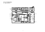
Page 133: ...133 14 Overall Simplified Block 14 1 Signal Flow SU ZT2 ...
Page 144: ...144 ...
Page 148: ...148 ...
Page 168: ...168 ...
Page 176: ...176 ...
Page 178: ...178 ...
Page 182: ...182 ...


