140
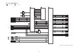
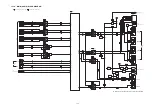
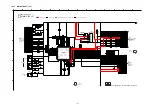
15.1.7. MAIN (SMPS) BLOCK DIAGRAM
FEED BACK
PC5501
A+7V
A-7V
S DET
SYS3.3V
D3.3V
+11V
VCC
SW 3.3V
CVCC18
HDMI POWER
HDMI CTRL
D5507
D5508
MAIN
TRANSFORMER
T5501
D5502
L5501
DZ5501
F1
AC IN
P5501
SWITCHING
REGULATOR
MIP2F50MSSCF
VCC
D
FB
4
TR
3
5
2
7
2
5
14
16
11
9
L5500
IC5501
VIN
1
VOUT
5
VC
3
C0CBCDC00014
VOLTAGE REGULATOR
IC5563
BK5V
QR5563
INVERTER
5
JW4205
CN2005
Q5561
SWITCH
IN
1
ON/OFF
OUT
2
3
C0CBCBG00013
VOLTAGE REGULATOR
IC2004
IN
1
ON/OFF
OUT
2
3
C0CBCAG00015
VOLTAGE REGULATOR
IC2233
IN
1
ON/OFF
OUT
2
3
C0CBCAG00015
VOLTAGE REGULATOR
IC2102
ON/OFF 3
IN
1
OUT
5
C0CBCBC00049
LDO
REGULATOR
IC2005
3,4
JW4205
CN2005
BK 4V
1,2
JW4205
CN2005
BK 2.5V
VIN
1
ON/OFF
5
VOUT
2
C0DBAYH00005
SWITCHING
REGULATOR
IC5562
VIN
1
ON/OFF
5
VOUT
2
C0DBAYH00005
SWITCHING
REGULATOR
IC5561
QR5562
INVERTER
PCONT
D5582
+5VA
D5563
SC-ZT2EE/GS(SU-ZT2EE/GS) MAIN(SMPS) BLOCK DIAGRAM
1
2
3
C0DAEMZ00001
SHUNT
REGULATOR
IC5502
VIN 3
VOUT
1
C0CBACC00046
VOLTAGE
REGULATOR
IC5571
D8001
D5571
5
12
CN4204
CN2004
1
16
CN4204
CN2004
VIN 2
VC
1
VOUT
4
C0DBEKG00004
VOLTAGE REGULATOR
IC5572
VIN 1
ON/OFF 5
VOUT
2
C0DBAYH00005
SWITCHING
REGULATOR
IC5504
VC 1
VIN 2
VOUT
4
C0DBEKG00004
SWITCHING
REGULATOR
IC5503
QR5503
INVERTER
QR5501
INVERTER
Q5506
INVERTER
Q5505
POWER CONTROL
Q5509
POWER CONTROL
Q5504
REGULATOR
Q5508
REGULATOR
QR5571
SWITCH
QR5502
INVERTER
D5581
D5583
Q5507
REGULATOR
QR5581
DC DETECT
QR5582
DC DETECT
D5584
D5587
D5586
D5506
D5505
D5511
15
10
D5504
SYS6V
FROM HDMI
TO HDMI
FROM
MAIN(SYSTEM CONTROL)
TO
MAIN(SYSTEM CONTROL)
FROM
MAIN(SYSTEM CONTROL)
FROM HDMI
Summary of Contents for VIERA Link SB-ZT2EE
Page 10: ...10 5 Location of Controls and Components 5 1 Main Unit SU ZT2 ...
Page 11: ...11 5 2 Speaker Unit SB ZT2 5 3 Remote Control ...
Page 12: ...12 6 Installation ...
Page 13: ...13 6 1 Basic Connections 6 1 1 Connecting equipment with HDMI terminal TV DVD recorder etc ...
Page 14: ...14 6 1 2 Connecting equipment without HDMI terminal DVD player VCR etc ...
Page 15: ...15 6 1 3 Connecting STB etc and audio terminals DVD player etc ...
Page 16: ...16 6 1 4 Other connections ...
Page 17: ...17 6 2 AC power supply connection ...
Page 18: ...18 7 Speaker setting SB ZT2 7 1 Setting the speakers Front and Surround speakers ...
Page 19: ...19 ...
Page 20: ...20 7 2 Setting surround speakers ...
Page 28: ...28 9 2 2 Speaker Unit SB ZT2 ...
Page 29: ...29 9 2 3 Speaker Unit SB ZT2 Wireless Link ...
Page 30: ...30 ...
Page 32: ...32 ...
Page 33: ...33 10 1 Main Parts Location Diagram 10 1 1 Main Unit SU ZT2 ...
Page 34: ...34 10 1 2 Speaker Unit SB ZT2 ...
Page 36: ...36 10 2 2 Speaker Unit SB ZT2 ...
Page 49: ...49 Step 4 Remove the Weight ...
Page 50: ...50 Step 5 Remove 10 screws ...
Page 54: ...54 Step 11 Remove 2 screws Step 12 Lift up to remove Arm Cover A ...
Page 56: ...56 Step 14 Tilt the Woofer Block in order as arrows shown to detach it from the Tweeter Block ...
Page 67: ...67 Step 3 Remove the heatsink with the IC5701 ...
Page 68: ...68 Step 4 Remove 1 screw Step 5 Remove IC5701 from the heatsink ...
Page 70: ...70 Step 4 Place the heatsink with the IC5701 onto the SMPS P C B ...
Page 82: ...82 Step 4 Remove 3 screws Step 5 Remove the Power Button ...
Page 87: ...87 Step 3 Remove 4 screws Step 4 Lift up to remove Woofer Speaker SP1 ...
Page 111: ...111 Step 11 Remove 3 screws ...
Page 112: ...112 Step 12 Remove the Light Panel Step 13 Remove the Power Button ...
Page 113: ...113 Step 14 Hold on to the P C B Holder and lift up the Input P C B as arrow shown ...
Page 114: ...114 Step 15 Place the D Amp P C B and Input P C B on an insulation sheet ...
Page 132: ...132 ...
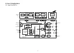
Page 133: ...133 14 Overall Simplified Block 14 1 Signal Flow SU ZT2 ...
Page 144: ...144 ...
Page 148: ...148 ...
Page 168: ...168 ...
Page 176: ...176 ...
Page 178: ...178 ...
Page 182: ...182 ...


