151
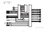
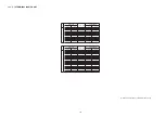
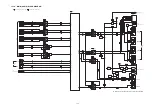
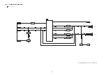
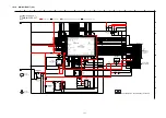
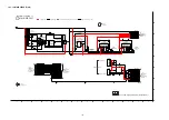
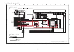
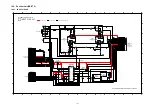
18.1.3. HDMI CIRCUIT (3/4)
P1
P4
P1
JK2202
HDMI AV
(AUX1 IN)
JK2201
HDMI AV
(BD/DVD IN)
A
HDMI CIRCUIT
SCHEMATIC DIAGRAM - 3
SC-ZT2EE/GS(SU-ZT2EE/GS) HDMI CIRCUIT
2/4
4/4
1/4
3/4
TO HDMI
SECTION (4/4)
TO HDMI
SECTION (1/4)
: HDMI AUDIO INPUT SIGNAL LINE
: HDMI VIDEO INPUT SIGNAL LINE
: AUDIO OUTPUT SIGNAL LINE
: VIDEO OUTPUT SIGNAL LINE
: +B SIGNAL LINE
I
1
2
3
4
5
6
7
8
9
10
11
12
13
14
K
L
J
M
O
P
N
I2C_DT
I2C_CK
SW_RST
47
R2216
1K
R2217
C2214
10
LB2209
SW_INT
CEC
4.7K
R2209
0.1
C2211
0.1
C2209
0.1
C2208
C2215
10
C2213
0.1
C2216
0.1
C2218
10
D2201
R2213
750
C2217
0.1
R2218 4.7K
R2219 4.7K
1
C2224
R2210 22K
C2223
0.1
33
R2221
0.1
C2212
C2210
0.1
61
40
59
56
57
52
53
48
49
43
44
41
42
46
47
45
51
50
55
54
58
60
63
65
72
71
73
69
68
70
79 80
75 76
74
78
77
66 67
64
62
38
36
34
32
30
25
27
28
26
22 21
24 23
29
31
20
33
18
17
19
35
15
16
13
12
11
14
37
9
7
5
3
1
2
4
6
8
10
39
IC2201
C2207
1000P
VA2212
VA2211
VA2210
VA2209
LB2204
VA2205
VA2207
VA2206
VA2208
VA2201
VA2203
VA2202
VA2204
47K
R2204
100K
R2203
LB2203
C2201
0.1
LB2201
R2201
0
LB2202
0.1
C2221
0.1
C2220
1000P
C2203
LB2205
0.1
C2222
47K
R2208
VA2224
VA2218
VA2222
VA2221
VA2217
VA2220
VA2219
VA2214
VA2213
VA2216
VA2215
LB2206
LB2208
LB2207
VA2213 - VA2220
C2202
0.1
R2207 100K
VA2223
C2205
1000P
1000P
C2206
G3
G4
G1
G2
5
3
4
7
9
8
6
1
2
10
13
15
17
19
18
16
14
11
12
C2204
1000P
G3
G4
G1
G2
5
3
4
7
9
8
6
1
2
10
13
15
17
19
18
16
14
11
12
33
R2220
R2205
0
47
R2215
LB2210
LB2211
1000P
C2219
RX0_5V
RX0_HPD
VA2221 - VA2224
VA2209 - VA2212
VA2201 - VA2208
EZJZ0V80008B
EZAEG2A50AX
EZJZ0V80008B
EZAEG2A50AX
LB2209 - LB2211
LB2205 - LB2208
LB2201 - LB2204
J0JHC0000021
J0JCC0000119
J0JCC0000119
C1AB00002977
B0ACCK000005
D2202
B0ACCK000005
HOT PLUG
AVCC33
ACEC_A
R2X0-
D0 GND
TMDS D0+
TMDS D1-
N.C.
CEC
CLK GND
TMDS CLK-
DDC_SCL
TMDS D0-
TMDS CLK+
DDC/CEC GND
DDC_SDA
+5V POWER
HPD2
[60] AGND
R2X1+
R2X0+
R2X1-
AVCC33
AGND
R2X2-
R2XC-
R2XC+
AVCC18
DSCL1
AGND
TMDS D2+
AGND
DDC/CEC GND
HOT PLUG
DDC_SCL
N.C.
DDC_SDA
+5V POWER
D2 GND
TMDS D0-
TMDS D1+
TMDS D0+
TMDS D1-
D1 GND
D0 GND
TMDS CLK+
CEC
CLK GND
TMDS CLK-
TMDS D2-
R1X1+
R1X2-
R1X1-
DSDA1
R1X2+
AVCC18
AVCC18
R1XC-
[41] R1X0-
DGND
I2CSEL/INT
HPD1
[42] R1X0+
R1XC+
AVCC33
RPWR1
ACEC_D
DSDA0
DSCL0
R0XC-
R0XC+
R0X0-
R0X0+
R0PWR5V
R0X1-
R0X1+
R0X2-
R0X2+
TXC+
AGND
AGND
HPD0
R0X0+
AVCC33
R0X0-
AVCC18
TXC-
R0X2-
DSCL0
RPWR0
R0X2+
DSDA0
AVCC18
DVCC18
[20] AGND
R0X1+
R0X1-
AGND
R0XC-
[19] R0XC+
EXTSWING
AVCC18
RESET
LSCL/EPSEL1
LSDA/EPSEL0
TPWR/I2CADR
AGND
DSCL2
DSDA2
RPWR2
R2X2+
DVCC18
AVCC18
TSCL
TSDA
RSVDL
HPDIN
DGND
TX1-
TX1+
[2] TX2-
TX0+
TX0-
[1] TX2+
AVCC18
D2 GND
TMDS D2-
TMDS D2+
D1 GND
TMDS D1+
SW_3.3V
GND
HDMI RECEIVER
47K
R2222
82K
R2223
IN1_5V
47K
R2224
82K
R2225
Summary of Contents for VIERA Link SB-ZT2EE
Page 10: ...10 5 Location of Controls and Components 5 1 Main Unit SU ZT2 ...
Page 11: ...11 5 2 Speaker Unit SB ZT2 5 3 Remote Control ...
Page 12: ...12 6 Installation ...
Page 13: ...13 6 1 Basic Connections 6 1 1 Connecting equipment with HDMI terminal TV DVD recorder etc ...
Page 14: ...14 6 1 2 Connecting equipment without HDMI terminal DVD player VCR etc ...
Page 15: ...15 6 1 3 Connecting STB etc and audio terminals DVD player etc ...
Page 16: ...16 6 1 4 Other connections ...
Page 17: ...17 6 2 AC power supply connection ...
Page 18: ...18 7 Speaker setting SB ZT2 7 1 Setting the speakers Front and Surround speakers ...
Page 19: ...19 ...
Page 20: ...20 7 2 Setting surround speakers ...
Page 28: ...28 9 2 2 Speaker Unit SB ZT2 ...
Page 29: ...29 9 2 3 Speaker Unit SB ZT2 Wireless Link ...
Page 30: ...30 ...
Page 32: ...32 ...
Page 33: ...33 10 1 Main Parts Location Diagram 10 1 1 Main Unit SU ZT2 ...
Page 34: ...34 10 1 2 Speaker Unit SB ZT2 ...
Page 36: ...36 10 2 2 Speaker Unit SB ZT2 ...
Page 49: ...49 Step 4 Remove the Weight ...
Page 50: ...50 Step 5 Remove 10 screws ...
Page 54: ...54 Step 11 Remove 2 screws Step 12 Lift up to remove Arm Cover A ...
Page 56: ...56 Step 14 Tilt the Woofer Block in order as arrows shown to detach it from the Tweeter Block ...
Page 67: ...67 Step 3 Remove the heatsink with the IC5701 ...
Page 68: ...68 Step 4 Remove 1 screw Step 5 Remove IC5701 from the heatsink ...
Page 70: ...70 Step 4 Place the heatsink with the IC5701 onto the SMPS P C B ...
Page 82: ...82 Step 4 Remove 3 screws Step 5 Remove the Power Button ...
Page 87: ...87 Step 3 Remove 4 screws Step 4 Lift up to remove Woofer Speaker SP1 ...
Page 111: ...111 Step 11 Remove 3 screws ...
Page 112: ...112 Step 12 Remove the Light Panel Step 13 Remove the Power Button ...
Page 113: ...113 Step 14 Hold on to the P C B Holder and lift up the Input P C B as arrow shown ...
Page 114: ...114 Step 15 Place the D Amp P C B and Input P C B on an insulation sheet ...
Page 132: ...132 ...
Page 133: ...133 14 Overall Simplified Block 14 1 Signal Flow SU ZT2 ...
Page 144: ...144 ...
Page 148: ...148 ...
Page 168: ...168 ...
Page 176: ...176 ...
Page 178: ...178 ...
Page 182: ...182 ...

