170
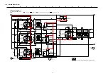
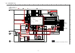
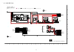
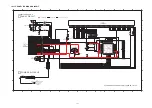
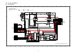
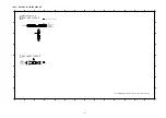
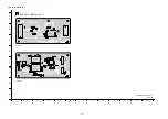
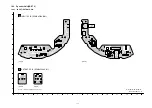
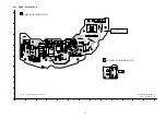
19.1.2. DSP P.C.B.
1
1
2
3
4
5
6
7
8
9
A
B
C
D
E
F
G
H
10
1
12
13
B
DSP P.C.B. (REPV0114F-T)
SC-ZT2EE/GS(SU-ZT2EE/GS)
DSP P.C.B.
(SIDE A)
(SIDE B)
0114F
0114F
0114F
0114F
C1006
C1007
C1008
C1009
C1010
C1011
C1012
C1013
C1014
C1015
C1016
C1020
C1023
C1024
C1025
C1027
C1028
C1029
C1031 C1032
C1033
C1036
C1037
C1038
C1039
C1041
C1043
C1044
C1045
C1048
C1050
C1051
C1052
C1053
C1054
C1055
C1058
C1080
C1081
C1082
C1084
C1085
C1086
C1087
C1049
C1059
CN1002
CNB2201
IC1000
IC1001
IC1002
IC1003
IC1005
L1000
L1001
L1002
L1003
L1004
LB1000
LB1001
LB1002
LB1003
LB1004
LB1005
LB1006
LB1007
LB1008
R1005
R1006
R1007
R1008
R1009
R1010
R101
1
R1012
R1015
R1016
R1017
R1018
R1019
R1020
R1021
R1022
R1023
R1024
R1030
R1031
R1033
R1051
R1052
R1053
R1054
R1055
RX1001
RX1002
RX1003
RX1004
RX1005
RX1006
RX1007
RX1008
X1000
R1036
C1035
IC1004
C1000
C1018
C1019
C1021
C1022
C1026
C1030
C1040 C1042
C1056
C1057
C1062
C1063
C1064
C1065
C1066
C1067
C1068
C1069
C1070
C1071
C1072
C1073
C1074
C1075
C1076
C1077
C1083
CN1001
CN1003
R1000
R1001
R1002
R1003
R1004
R1013
R1014
R1025
R1027
R1028
R1029
R1032
R1035
C1060
30
29
28
27
26
25
24
23
22
21
20
19
18
17
16
15
14
13
12
11
10
9
8
7
6
5
4
3
2
1
11
10
9
8
7
6
5
4
3
2
1
22
21
20
19
18
17
16
15
14
13
12
PbF
PbF
1
5
6
7
8
9
2
3
4
10
11
12
13
14
1
5
6
7
8
9
2
3
4
10
12
11
38
35
30
25
20
15
10
5
1
128
125
115
110
105
103
102100
95
90
85
80
75
70
65
64
60
55
50
45
40
39
1
5
10
1516
17
20
25
30
32
33
35
40
45
48
49
50
55
60
64
3 4
2
5
1
5
4
1 2 3
1
5
10
15
20
25
26
30
35
40
45
50
3
2
1
4
5
6
Summary of Contents for VIERA Link SB-ZT2EE
Page 10: ...10 5 Location of Controls and Components 5 1 Main Unit SU ZT2 ...
Page 11: ...11 5 2 Speaker Unit SB ZT2 5 3 Remote Control ...
Page 12: ...12 6 Installation ...
Page 13: ...13 6 1 Basic Connections 6 1 1 Connecting equipment with HDMI terminal TV DVD recorder etc ...
Page 14: ...14 6 1 2 Connecting equipment without HDMI terminal DVD player VCR etc ...
Page 15: ...15 6 1 3 Connecting STB etc and audio terminals DVD player etc ...
Page 16: ...16 6 1 4 Other connections ...
Page 17: ...17 6 2 AC power supply connection ...
Page 18: ...18 7 Speaker setting SB ZT2 7 1 Setting the speakers Front and Surround speakers ...
Page 19: ...19 ...
Page 20: ...20 7 2 Setting surround speakers ...
Page 28: ...28 9 2 2 Speaker Unit SB ZT2 ...
Page 29: ...29 9 2 3 Speaker Unit SB ZT2 Wireless Link ...
Page 30: ...30 ...
Page 32: ...32 ...
Page 33: ...33 10 1 Main Parts Location Diagram 10 1 1 Main Unit SU ZT2 ...
Page 34: ...34 10 1 2 Speaker Unit SB ZT2 ...
Page 36: ...36 10 2 2 Speaker Unit SB ZT2 ...
Page 49: ...49 Step 4 Remove the Weight ...
Page 50: ...50 Step 5 Remove 10 screws ...
Page 54: ...54 Step 11 Remove 2 screws Step 12 Lift up to remove Arm Cover A ...
Page 56: ...56 Step 14 Tilt the Woofer Block in order as arrows shown to detach it from the Tweeter Block ...
Page 67: ...67 Step 3 Remove the heatsink with the IC5701 ...
Page 68: ...68 Step 4 Remove 1 screw Step 5 Remove IC5701 from the heatsink ...
Page 70: ...70 Step 4 Place the heatsink with the IC5701 onto the SMPS P C B ...
Page 82: ...82 Step 4 Remove 3 screws Step 5 Remove the Power Button ...
Page 87: ...87 Step 3 Remove 4 screws Step 4 Lift up to remove Woofer Speaker SP1 ...
Page 111: ...111 Step 11 Remove 3 screws ...
Page 112: ...112 Step 12 Remove the Light Panel Step 13 Remove the Power Button ...
Page 113: ...113 Step 14 Hold on to the P C B Holder and lift up the Input P C B as arrow shown ...
Page 114: ...114 Step 15 Place the D Amp P C B and Input P C B on an insulation sheet ...
Page 132: ...132 ...
Page 133: ...133 14 Overall Simplified Block 14 1 Signal Flow SU ZT2 ...
Page 144: ...144 ...
Page 148: ...148 ...
Page 168: ...168 ...
Page 176: ...176 ...
Page 178: ...178 ...
Page 182: ...182 ...

