183
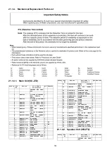
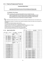
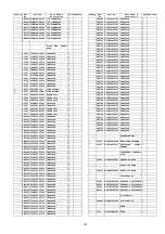
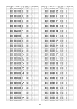
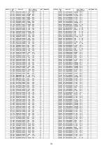
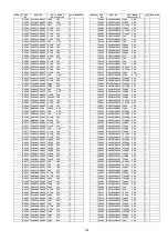
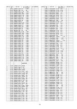
21.1.4. Mechanical Replacement Parts List
21.1.4.1. Main Unit (SU-ZT2)
21.1.4.2. Speaker Unit (SB-ZT2)
Safety
Ref.
No.
Part No.
Part Name &
Description
QTY Remarks
CABINET AND CHAS-
SIS
1
REX1304
1P WIRE (WIRELESS-
BTM CHASSIS ;
TP4701)
1
2
REX1305
7P WIRE (MAIN-HDMI
; JW4205)
1
3
REE1503
12P FFC (MAIN-DSP) 1
4
REE1504
14P FFC (MAIN-DSP) 1
5
REE1505
15P FFC (MAIN-
HDMI)
1
6
REE1506
16P FFC (MAIN-
HDMI)
1
7
REE1507
19P FFC (WIRELESS-
MAIN)
1
8
RWJ2V03205SS 3P WIRE (PANEL-
POWER; JW4602)
1
9
RMNV0063A-K
FL HOLDER
1
10
RMNX0253
LED HOLDER
1
11
RGR0393A-K
REAR PANEL
1
GS
11
RGR0393A-M
REAR PANEL
1
EE
12
RHD30111-31
SCREW
11
13
RHD30119-S
SCREW
10
14
RKA0105-KJ
CUSHION
4
15
RMK0726-1
BOTTOM CHASSIS
1
16
RMR1359-W
PCB SUPPORT
3
17
RMZ1028
INSULATOR SHEET B
1
18
RSCV0082
HDMI SUPPORT CHAS-
SIS
1
19
RFKGCZT2EE-K FRONT CABINET
ASS’Y
1
20
REE1508
22P FFC (PANEL-
MAIN)
1
22
RGL0724-Q
LIGHTING RING
1
23
RGU2643-K
POWER BUTTON
1
24
RGU2644-K
SELECTOR BUTTON
1
25
RGWX0116-K
VOLUME KNOB
1
26
RHD26046
SCREW
6
27
XSN3+4FJ
SCREW
3
28
RHD30007-K2J SCREW
2
29
RHD30119-K
SCREW
3
30
RKM0613-K
TOP CABINET
1
31
RSC0824
RADIATOR SHEET
1
32
REX1304
1P WIRE (PWR BTN-
BTM CHASSIS ;
TP4612)
1
33
REX1378-1
1P WIRE (MAIN-
MAIN)
1
34
RMV0336
CHASSIS SHEET
1
35
J0KD00000068 FERRITE CORE
1
36
RHDX30005-1
SCREW
1
37
RMC0709
VCR EARTH ANGLE
1
38
RMQ1752
FRONT SHIELD
1
39
RMZ1055
INSULATION SHEET
1
40
RSC0734
PANEL EARTH PLATE
2
Safety
Ref.
No.
Part No.
Part Name &
Description
QTY Remarks
CABINET AND CHAS-
SIS
Safety
Ref.
No.
Part No.
Part Name &
Description
QTY Remarks
Summary of Contents for VIERA Link SB-ZT2EE
Page 10: ...10 5 Location of Controls and Components 5 1 Main Unit SU ZT2 ...
Page 11: ...11 5 2 Speaker Unit SB ZT2 5 3 Remote Control ...
Page 12: ...12 6 Installation ...
Page 13: ...13 6 1 Basic Connections 6 1 1 Connecting equipment with HDMI terminal TV DVD recorder etc ...
Page 14: ...14 6 1 2 Connecting equipment without HDMI terminal DVD player VCR etc ...
Page 15: ...15 6 1 3 Connecting STB etc and audio terminals DVD player etc ...
Page 16: ...16 6 1 4 Other connections ...
Page 17: ...17 6 2 AC power supply connection ...
Page 18: ...18 7 Speaker setting SB ZT2 7 1 Setting the speakers Front and Surround speakers ...
Page 19: ...19 ...
Page 20: ...20 7 2 Setting surround speakers ...
Page 28: ...28 9 2 2 Speaker Unit SB ZT2 ...
Page 29: ...29 9 2 3 Speaker Unit SB ZT2 Wireless Link ...
Page 30: ...30 ...
Page 32: ...32 ...
Page 33: ...33 10 1 Main Parts Location Diagram 10 1 1 Main Unit SU ZT2 ...
Page 34: ...34 10 1 2 Speaker Unit SB ZT2 ...
Page 36: ...36 10 2 2 Speaker Unit SB ZT2 ...
Page 49: ...49 Step 4 Remove the Weight ...
Page 50: ...50 Step 5 Remove 10 screws ...
Page 54: ...54 Step 11 Remove 2 screws Step 12 Lift up to remove Arm Cover A ...
Page 56: ...56 Step 14 Tilt the Woofer Block in order as arrows shown to detach it from the Tweeter Block ...
Page 67: ...67 Step 3 Remove the heatsink with the IC5701 ...
Page 68: ...68 Step 4 Remove 1 screw Step 5 Remove IC5701 from the heatsink ...
Page 70: ...70 Step 4 Place the heatsink with the IC5701 onto the SMPS P C B ...
Page 82: ...82 Step 4 Remove 3 screws Step 5 Remove the Power Button ...
Page 87: ...87 Step 3 Remove 4 screws Step 4 Lift up to remove Woofer Speaker SP1 ...
Page 111: ...111 Step 11 Remove 3 screws ...
Page 112: ...112 Step 12 Remove the Light Panel Step 13 Remove the Power Button ...
Page 113: ...113 Step 14 Hold on to the P C B Holder and lift up the Input P C B as arrow shown ...
Page 114: ...114 Step 15 Place the D Amp P C B and Input P C B on an insulation sheet ...
Page 132: ...132 ...
Page 133: ...133 14 Overall Simplified Block 14 1 Signal Flow SU ZT2 ...
Page 144: ...144 ...
Page 148: ...148 ...
Page 168: ...168 ...
Page 176: ...176 ...
Page 178: ...178 ...
Page 182: ...182 ...


