184
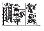
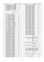
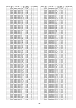
21.1.4.3. Packaging (SC-ZT2)
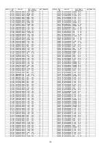
100
REX1346-1
1P BLACK WIRE
(SMPS-AC)
1
101
REX1356-1
1P RED WIRE (SMPS-
AC)
1
102
XTB3+8JFJ
SCREW
1
103
XTV3+6FFJ
SCREW
1
104
REX1347
10P WIRE (DAMP-
SMPS);JW5802
1
105
REX1348-2
2P WIRE (DAMP-
WOOFER);W6003
1
106
REX1350-J
15P FFC (DAMP-
INPUT)
1
107
REZ1960-1
WIRE (EXTEND-DAMP) 1
109
REX1358
COAXIAL CABLE (RX-
EXTEND)
1
110
RMF0245D
ABSORBER (WOOFER)
1
111
RGK2190-T
WOOFER COVER ORNA-
MENT
1
112
RGL0723-Q
LIGHT PANEL
1
113
RGN2979K-K
SPEC SHEET
1
GS
113
RGN2979L-K
SPEC SHEET
1
EE
114
RGN2980J-K
CAUTION LABEL
1
EE
114
RGN2980K-K
CAUTION LABEL
1
GS
115
RGU2645B-K
POWER BUTTON
1
116
RHD26046
SCREW
13
117
XTB26+12GFJ
SCREW
27
118
RHD26043-1
SCREW
3
119
RKA0181A-K
LEG CUSHION
6
120
RYQ0715-K1
MID CABINET ASS’Y
1
121
RKP0110-K
BOTTOM CABINET
1
122
RMA2200-1
SHEET METAL
1
123
RMA2201-2
WEIGHT
1
124
RMF0428-1
PORT NOISE
ABSORBER
1
125
RMNX0224-1
PCB HOLDER
2
127
XTB3+10GFJK
SCREW
1
128
RXM0086Z
ANTENNA
1
131
RYQ0710-W
PORT ASSY (A/B)
1
132
RMF0428A
SEALER
1
133
RMQ1740B
SEALER
1
134
RYQ0711-W
PORT ASSY (C,D)
1
135
RMQ1740A-1
EPT SEALER
1
137
RYQ0714A-T
WOOFER COVER ASS’Y 1
138
RMR1937-W
WIRE PROTECTOR
1
139
XTB4+10JFJ
SCREW
4
140
XYN4+F20FJ
SCREW
3
141
REX1353
WIRE (EXTENSION
RELAY-TWEETER)
1
142
RGK2184-Q
ANTENNA FRONT
ORNAMENT
1
143
RGK2186A-T
ANTENNA COVER A
1
144
RGK2187-T
PIPE BOTTOM COVER
1
145
RGK2188-T
ARM COVER-A
1
146
RGK2189-K
ARM COVER B
1
147
RGK2194-T
ANTENNA COVER B
1
148
RYQ0716-K
PREPARED NET ASS’Y 1
149
RHD40030
SCREW
2
150
RKM0614-T
PIPE
1
151
RMA2196-1
TWEETER BASE FRAME 1
152
RMA2197-1
ARM
1
153
RMA2203
ANTENNA HOLDER
1
155
RMF0421A
BLIND SHEET-A
1
156
RMF0421B
BLIND SHEET-B
3
157
RMF0421C
BLIND SHEET-C
1
158
RMF0429
SOUND ABSORBER
5
159
RMQ1722B
HIMELON
4
160
RMQ1722A
HIMELON (FOR ANT
CABLE)
1
162
RMQ1722J
HIMELON (FOR
TWEETER)
4
166
XTS2+6GFJ
SCREW
2
167
XSB3+8FJK
SCREW
4
168
XTB3+6JFJK
SCREW
7
169
XTB4+6JFJK
SCREW
8
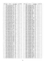
Safety
Ref.
No.
Part No.
Part Name &
Description
QTY Remarks
170
XTN2+6JFJK
SCREW
4
171
RMQ1750
HIMELON
4
172
RMQ1751
HIMELON
2
173
XYN4+J30FJ
M4 SCREW
1
174
RMF0438
PET SHEET
4
176
RMF0446
ARM BBD C/M SHEET
A
2
177
RMF0447
ARM BBD C/M SHEET
B
1
178
RMF0448
ARM BBD C/M SHEET
C
1
179
RMQ1757-1
PCB CUSHION
2
180
RMX0451
PIPE SPACER
1
SPEAKERS
SP1
L0AA12A00024 WOOFER
1
SP2
EAS10D85M
TWEETER
1
SP3
EAS10D85M
TWEETER
1
SP4
EAS10D85M
TWEETER
1
SP5
EAS10D85M
TWEETER
1
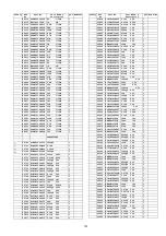
Safety
Ref.
No.
Part No.
Part Name &
Description
QTY Remarks
PACKING MATERIALS
P1
RPG9217
PACKING CASE
1
EE
P1
RPG9219
PACKING CASE
1
GS
P2
RPF0481
PROTECTION BAG
2
P3
RPF0479-1
MIRAMAT BAG
2
P4
RPN2105-1
POLYFOAM
1
P5
RPN2106-2
POLYFOAM
1
P6
RPFX0262
MIRAMAT BAG
1
ACCESSORIES
A1
N2QAYB000417 REMOTE CONTROL
1
A1-1
RKK-PT470EBK R/C BATTERY COVER
1
A2
K2CA2CA00031 AC CORD
3
GS
A2
K2CP2CA00001 AC CORD
3
GS
A2
K2CQ2CA00007 AC CORD
3
A2
K2CZ3YY00005 AC CORD
3
GS
A3
VQT2R71
O/I
1
GS
A3
VQT2U14
O/I
1
EE
A3
VQT2U15
O/I
1
GS
A4
RFA3045-2
LEG CUSHION ASS’Y
1
Safety
Ref.
No.
Part No.
Part Name &
Description
QTY Remarks
Summary of Contents for VIERA Link SB-ZT2EE
Page 10: ...10 5 Location of Controls and Components 5 1 Main Unit SU ZT2 ...
Page 11: ...11 5 2 Speaker Unit SB ZT2 5 3 Remote Control ...
Page 12: ...12 6 Installation ...
Page 13: ...13 6 1 Basic Connections 6 1 1 Connecting equipment with HDMI terminal TV DVD recorder etc ...
Page 14: ...14 6 1 2 Connecting equipment without HDMI terminal DVD player VCR etc ...
Page 15: ...15 6 1 3 Connecting STB etc and audio terminals DVD player etc ...
Page 16: ...16 6 1 4 Other connections ...
Page 17: ...17 6 2 AC power supply connection ...
Page 18: ...18 7 Speaker setting SB ZT2 7 1 Setting the speakers Front and Surround speakers ...
Page 19: ...19 ...
Page 20: ...20 7 2 Setting surround speakers ...
Page 28: ...28 9 2 2 Speaker Unit SB ZT2 ...
Page 29: ...29 9 2 3 Speaker Unit SB ZT2 Wireless Link ...
Page 30: ...30 ...
Page 32: ...32 ...
Page 33: ...33 10 1 Main Parts Location Diagram 10 1 1 Main Unit SU ZT2 ...
Page 34: ...34 10 1 2 Speaker Unit SB ZT2 ...
Page 36: ...36 10 2 2 Speaker Unit SB ZT2 ...
Page 49: ...49 Step 4 Remove the Weight ...
Page 50: ...50 Step 5 Remove 10 screws ...
Page 54: ...54 Step 11 Remove 2 screws Step 12 Lift up to remove Arm Cover A ...
Page 56: ...56 Step 14 Tilt the Woofer Block in order as arrows shown to detach it from the Tweeter Block ...
Page 67: ...67 Step 3 Remove the heatsink with the IC5701 ...
Page 68: ...68 Step 4 Remove 1 screw Step 5 Remove IC5701 from the heatsink ...
Page 70: ...70 Step 4 Place the heatsink with the IC5701 onto the SMPS P C B ...
Page 82: ...82 Step 4 Remove 3 screws Step 5 Remove the Power Button ...
Page 87: ...87 Step 3 Remove 4 screws Step 4 Lift up to remove Woofer Speaker SP1 ...
Page 111: ...111 Step 11 Remove 3 screws ...
Page 112: ...112 Step 12 Remove the Light Panel Step 13 Remove the Power Button ...
Page 113: ...113 Step 14 Hold on to the P C B Holder and lift up the Input P C B as arrow shown ...
Page 114: ...114 Step 15 Place the D Amp P C B and Input P C B on an insulation sheet ...
Page 132: ...132 ...
Page 133: ...133 14 Overall Simplified Block 14 1 Signal Flow SU ZT2 ...
Page 144: ...144 ...
Page 148: ...148 ...
Page 168: ...168 ...
Page 176: ...176 ...
Page 178: ...178 ...
Page 182: ...182 ...

