83
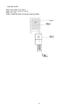
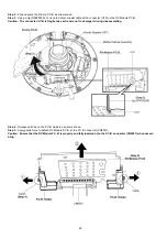
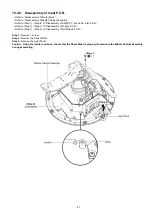
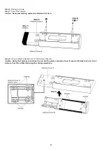
Caution : Ensure that the Power Button Switch is pushed down to ‘On’ position before fixing the Power Button.
Step 6 :
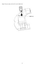
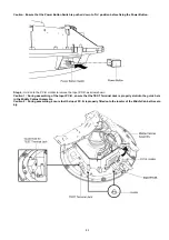
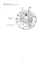
Hold on to the P.C.B. Holder to remove the Input P.C.B. as arrow shown.
Caution 1 : During assembling of the Input P.C.B., ensure that the TEST Terminal Jack is properly slot into the guide hole
in the Middle Cabinet Assembly.
Caution 2 : During assembling, ensure that the Input P.C.B. is properly fitted onto the locator of the Middle Cabinet Assem-
bly.
Summary of Contents for VIERA Link SB-ZT2EE
Page 10: ...10 5 Location of Controls and Components 5 1 Main Unit SU ZT2 ...
Page 11: ...11 5 2 Speaker Unit SB ZT2 5 3 Remote Control ...
Page 12: ...12 6 Installation ...
Page 13: ...13 6 1 Basic Connections 6 1 1 Connecting equipment with HDMI terminal TV DVD recorder etc ...
Page 14: ...14 6 1 2 Connecting equipment without HDMI terminal DVD player VCR etc ...
Page 15: ...15 6 1 3 Connecting STB etc and audio terminals DVD player etc ...
Page 16: ...16 6 1 4 Other connections ...
Page 17: ...17 6 2 AC power supply connection ...
Page 18: ...18 7 Speaker setting SB ZT2 7 1 Setting the speakers Front and Surround speakers ...
Page 19: ...19 ...
Page 20: ...20 7 2 Setting surround speakers ...
Page 28: ...28 9 2 2 Speaker Unit SB ZT2 ...
Page 29: ...29 9 2 3 Speaker Unit SB ZT2 Wireless Link ...
Page 30: ...30 ...
Page 32: ...32 ...
Page 33: ...33 10 1 Main Parts Location Diagram 10 1 1 Main Unit SU ZT2 ...
Page 34: ...34 10 1 2 Speaker Unit SB ZT2 ...
Page 36: ...36 10 2 2 Speaker Unit SB ZT2 ...
Page 49: ...49 Step 4 Remove the Weight ...
Page 50: ...50 Step 5 Remove 10 screws ...
Page 54: ...54 Step 11 Remove 2 screws Step 12 Lift up to remove Arm Cover A ...
Page 56: ...56 Step 14 Tilt the Woofer Block in order as arrows shown to detach it from the Tweeter Block ...
Page 67: ...67 Step 3 Remove the heatsink with the IC5701 ...
Page 68: ...68 Step 4 Remove 1 screw Step 5 Remove IC5701 from the heatsink ...
Page 70: ...70 Step 4 Place the heatsink with the IC5701 onto the SMPS P C B ...
Page 82: ...82 Step 4 Remove 3 screws Step 5 Remove the Power Button ...
Page 87: ...87 Step 3 Remove 4 screws Step 4 Lift up to remove Woofer Speaker SP1 ...
Page 111: ...111 Step 11 Remove 3 screws ...
Page 112: ...112 Step 12 Remove the Light Panel Step 13 Remove the Power Button ...
Page 113: ...113 Step 14 Hold on to the P C B Holder and lift up the Input P C B as arrow shown ...
Page 114: ...114 Step 15 Place the D Amp P C B and Input P C B on an insulation sheet ...
Page 132: ...132 ...
Page 133: ...133 14 Overall Simplified Block 14 1 Signal Flow SU ZT2 ...
Page 144: ...144 ...
Page 148: ...148 ...
Page 168: ...168 ...
Page 176: ...176 ...
Page 178: ...178 ...
Page 182: ...182 ...

