9
4 Specifications
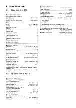
4.1.
Main Unit (SU-ZT2)
4.2.
Speaker Unit (SB-ZT2)
Q
PRE AMPLIFIER SECTION
Input sensitivity / Input Impedance
TV, AUX3
600 mV / 47 k
Ω
S/N ratio (IHF A)
BD/DVD, TV, AUX1, AUX2 (Digital
Input)
80 dB (IHF ‘66)
Tone controls
BASS
50 Hz, +6 to -6 dB
TREBLE
20 kHz, +6 to -6 dB
Input / Output terminal
Audio IN
(TV, AUX3)
2
Digital Audio IN
Optical 1, 2 (TV, AUX2)
2
Audio OUT
(Front L/R, Surround L/R)
4
Subwoofer Output
1
Headphone Output (16 to 64
Ω
)
1
AV
HDMI IN (BD/DVD, AUX1)
2
HDMI OUT (TO TV (ARC))
1
This system supports “HDAVI Control 4” function.
Q
MAIN UNIT GENERAL
Power supply
AC 110 to 240 V, 50/60 Hz
Power consumption
16 W
In standby condition
0.5 W
In standby condition (HDMI off
mode)
0.2 W
Dimensions (WxHxD)
430mm x 59mm x 262mm
Mass
Approx. 2 kg
Operating temperature range
0
°
C to 40
°
C
Operating humidity range
20% to 80% RH (no condensa-
tion)
Q
WIRELESS SECTION
Frequency of the using band
2.4000 GHz to 2.4835 GHz
Number of using channels
3
The reaching distance
15m *
1
*1 It is under the condition as follows.
At same room indoor, there is not an obstacle between the main unit
and the speaker.
And installing a main unit in the position with equal to or more than 50
cm height.
Q
POWER AMPLIFIER SECTION*
2
RMS output power (at AC 220 to 240 V)
10% total harmonic distortion
Woofer Speaker ch
60 W (100 Hz, 3
Ω
)
Mid High Speaker ch
20 W (1 kHz, 8
Ω
)
System Total Power*
3
160 W (80 W + 80 W)
DIN output power (at AC 220 to 240 V)
1.0% total harmonic distortion
100Hz Woofer Speaker ch
40 W (3
Ω
)
1kHz Mid High Speaker ch
15 W (8
Ω
)
System Total Power*
3
110 W (55 W + 55 W)
Q
SPEAKER SECTION*
2
2 way 5 speakers system (Bass reflex type)
Woofer part
12 cm cone type x 1
Mid High part
2.4 x 10 cm flat type x 4
Q
SPEAKER GENERAL*
2
Power supply
AC 110 to 240 V, 50/60 Hz
Power consumption
20 W
Wireless link standby
0.8 W
In standby condition
0.15 W
Dimensions (WxHxD)
290mm x 1231mm x 290mm
Mass [Weight]
Approx. 3.9 kg
Operating temperature range
0
°
C to 40
°
C
Operating humidity range
20% to 80% RH (no condensa-
tion)
*2
: per 1 speaker
*3
: use 2 speakers
Note:
1. Specifications are subject to change without notice.
2. Total harmonic distortion is measured by the digital spectrum ana-
lyzer.
2. Total harmonic distortion is measured by using AES17 filter.
Q
System : SC-ZT2EE-K
Music center: SU-ZT2EE-K
Speaker: SB-ZT2EE-K1
Q
System : SC-ZT2GS-K
Music center: SU-ZT2GS-K
Speaker: SB-ZT2GS-K1
Summary of Contents for VIERA Link SB-ZT2EE
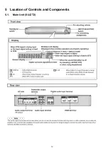
Page 10: ...10 5 Location of Controls and Components 5 1 Main Unit SU ZT2 ...
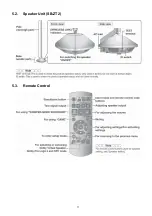
Page 11: ...11 5 2 Speaker Unit SB ZT2 5 3 Remote Control ...
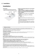
Page 12: ...12 6 Installation ...
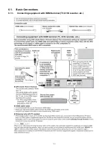
Page 13: ...13 6 1 Basic Connections 6 1 1 Connecting equipment with HDMI terminal TV DVD recorder etc ...
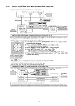
Page 14: ...14 6 1 2 Connecting equipment without HDMI terminal DVD player VCR etc ...
Page 15: ...15 6 1 3 Connecting STB etc and audio terminals DVD player etc ...
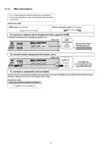
Page 16: ...16 6 1 4 Other connections ...
Page 17: ...17 6 2 AC power supply connection ...
Page 18: ...18 7 Speaker setting SB ZT2 7 1 Setting the speakers Front and Surround speakers ...
Page 19: ...19 ...
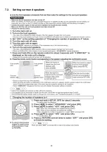
Page 20: ...20 7 2 Setting surround speakers ...
Page 28: ...28 9 2 2 Speaker Unit SB ZT2 ...
Page 29: ...29 9 2 3 Speaker Unit SB ZT2 Wireless Link ...
Page 30: ...30 ...
Page 32: ...32 ...
Page 33: ...33 10 1 Main Parts Location Diagram 10 1 1 Main Unit SU ZT2 ...
Page 34: ...34 10 1 2 Speaker Unit SB ZT2 ...
Page 36: ...36 10 2 2 Speaker Unit SB ZT2 ...
Page 49: ...49 Step 4 Remove the Weight ...
Page 50: ...50 Step 5 Remove 10 screws ...
Page 54: ...54 Step 11 Remove 2 screws Step 12 Lift up to remove Arm Cover A ...
Page 56: ...56 Step 14 Tilt the Woofer Block in order as arrows shown to detach it from the Tweeter Block ...
Page 67: ...67 Step 3 Remove the heatsink with the IC5701 ...
Page 68: ...68 Step 4 Remove 1 screw Step 5 Remove IC5701 from the heatsink ...
Page 70: ...70 Step 4 Place the heatsink with the IC5701 onto the SMPS P C B ...
Page 82: ...82 Step 4 Remove 3 screws Step 5 Remove the Power Button ...
Page 87: ...87 Step 3 Remove 4 screws Step 4 Lift up to remove Woofer Speaker SP1 ...
Page 111: ...111 Step 11 Remove 3 screws ...
Page 112: ...112 Step 12 Remove the Light Panel Step 13 Remove the Power Button ...
Page 113: ...113 Step 14 Hold on to the P C B Holder and lift up the Input P C B as arrow shown ...
Page 114: ...114 Step 15 Place the D Amp P C B and Input P C B on an insulation sheet ...
Page 132: ...132 ...
Page 133: ...133 14 Overall Simplified Block 14 1 Signal Flow SU ZT2 ...
Page 144: ...144 ...
Page 148: ...148 ...
Page 168: ...168 ...
Page 176: ...176 ...
Page 178: ...178 ...
Page 182: ...182 ...


