background image

3

2 Warning

2.1.

Prevention of Electrostatic Discharge (ESD) to Electrostatically Sensi-
tive (ES) Devices

Some semiconductor (solid state) devices can be damaged easily by static electricity.  Such components commonly are called Elec-
trostatically Sensitive (ES) Devices. Examples of typical ES devices are integrated circuits and some field-effect transistors and
semiconductor  [chip] components.  The following techniques should be used to help reduce the incidence of component damage
caused by electrostatic discharge (ESD).

1. Immediately before handling any semiconductor component or semiconductor-equipped assembly, drain off any ESD on your

body by touching a known earth ground.  Alternatively, obtain and wear a commercially available discharging ESD wrist strap,
which should be removed for potential shock reasons prior to applying power to the unit under test.

2. After removing an electrical assembly equipped with ES devices, place the assembly on a conductive surface such as alumi-

num foil, to prevent electrostatic charge buildup or exposure of the assembly.

3. Use only a grounded-tip soldering iron to solder or unsolder ES devices.
4. Use only an anti-static solder removal device.  Some solder removal devices not classified as [anti-static (ESD protected)] can

generate electrical charge sufficient to damage ES devices.

5. Do not use freon-propelled chemicals.   These can generate electrical charges sufficient to damage ES devices.
6. Do not remove a replacement ES device from its protective package until immediately before you are ready to install it. (Most

replacement ES devices are packaged with leads electrically shorted together by conductive foam, aluminum foil or compara-
ble conductive material).

7. Immediately before removing the protective material from the leads of a replacement ES device, touch the protective material

to the chassis or circuit assembly into which the device will be installed.

Caution

Be sure no power is applied to the chassis or circuit, and observe all other safety precautions.

8. Minimize bodily motions when handling unpackaged replacement ES devices. (Otherwise ham less motion such as the brush-

ing together of your clothes fabric or the lifting of your foot from a carpeted floor can generate static electricity (ESD) sufficient
to damage an ES device).

All manuals and user guides at all-guides.com

Summary of Contents for Viera TC-26LX85

Page 1: ...hts reserved Unauthorized copying and distribu tion is a violation of law ORDER NO MTNC080206CE B05 Canada B07 26 inch 32 inch Class LCD HDTV Model No TC 26LX85 TC 32LX85 LH70 Chassis All manuals and user guides at all guides com a l l g u i d e s c o m ...

Page 2: ...d each exposed metal lic cabinet part on the equipment such as screwheads connectors control shafts etc When the exposed metal lic part has a return path to the chassis the reading should be 100 Mohm and over When the exposed metal does not have a return path to the chassis the reading must be 1 1 2 Leakage Current Hot Check See Figure 1 1 Plug the AC cord directly into the AC outlet Do not use an...

Page 3: ... only a grounded tip soldering iron to solder or unsolder ES devices 4 Use only an anti static solder removal device Some solder removal devices not classified as anti static ESD protected can generate electrical charge sufficient to damage ES devices 5 Do not use freon propelled chemicals These can generate electrical charges sufficient to damage ES devices 6 Do not remove a replacement ES device...

Page 4: ...elting point than standard solder Typically the melting point is 50 70 F 30 40 C higher Please use a high temperature soldering iron and set it to 700 20 F 370 10 C Pb free solder will tend to splash when heated too high about 1100 F or 600 C If you must use Pb solder please completely remove all of the Pb free solder on the pins or solder area before applying Pb sol der If this is not practical b...

Page 5: ... Board Name Function A Board Rear Terminal AV Swich MCU Audio Video Processor LVDS Tuner V Board Remote Receiver LED P Board Power AC DC DC DC Control Panel Assy Control Button Power switch None serviceable Control Panel Assy should be exchanged for service horizontal frequency kHz vertical frequency kHz COMPONENT HDMI 525 480 60i 15 73 59 94 525 480 60p 31 47 59 94 750 720 60p 45 00 59 94 1 125 1...

Page 6: ...ion Terminals VIDEO IN 1 VIDEO RCA PIN Type 1 1 0 V p p 75 Ω S VIDEO Mini DIN 4 pin Y 1 0 V p p 75 Ω C 0 286 V p p 75 Ω AUDIO L R RCA PIN Type 2 0 5 V rms VIDEO IN 2 VIDEO RCA PIN Type 1 1 0 V p p 75 Ω AUDIO L R RCA PIN Type 2 0 5 V rms COMPONENT IN 1 Y 1 0 V p p including synchronization PB PR 0 35 V p p AUDIO L R RCA PIN Type 2 0 5 V rms HDMI 1 3 TYPE A Connector 3 This TV supports HDAVI Control...

Page 7: ...ontents of adjustment mode Value is shown as a hexadecimal number Preset value differs depending on models After entering the adjustment mode take note of the value in each item before starting adjustment 5 1 3 How to exit Switch off the power with the POWER button on the main unit or the POWER button on the remote control Main item Sub item Sample Data Remark ADJUST CONTRAST 000 COLOR 42 TINT 00 ...

Page 8: ...on except 2nd and 1st occurrence after shipment will be cleared by Self check indication and forced to factory ship ment setting 5 2 3 POWER ON TIME COUNT Note To display TIME COUNT menu highlight position then press MUTE for 3sec Time Cumulative power on time indicated hour minute by decimal Count Number of ON times by decimal Note This indication will not be cleared by either of the self checks ...

Page 9: ... Off give priority to a last memory Channel Select channel when input signal is RF Set the channel each time power is switched on Selection Any channel number or means the channel when turns off Volume Adjust the volume when each time power is switched on Range 0 to 100 Vol Max Adjust maximum volume Range 0 to 100 OSD Ctrl Restrict the OSD Selection OFF PATTERN1 OFF No restriction PATTERN1 restric...

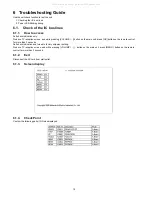
Page 10: ...n on the main unit press OK button on the remote control for more than 3 seconds Self check indication and forced to factory shipment setting Produce TV reception screen and while pressing VOLUME button on the main unit press MENU button on the remote control for more than 3 seconds 6 1 2 Exit Disconnect the AC cord from wall outlet 6 1 3 Screen display 6 1 4 Check Point Confirm the following part...

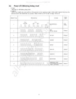
Page 11: ...ts When an abnormality has occurred the unit the protection circuit operates and reset to the stand by mode At this time the defective block can be identified by the number of blinks of the Power LED on the front panel of the unit All manuals and user guides at all guides com a l l g u i d e s c o m ...

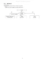
Page 12: ...o Power First check point There are following 2 states of No Power indication by power LED 1 No lit 2 Red is lit then turns red blinking a few seconds later See 6 2 All manuals and user guides at all guides com ...

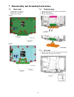
Page 13: ...ove the rear cover 32 inch 26 inch 7 2 Pedestal assy 1 Lay down the unit so that the rear cover faces upward 2 Remove the 4 screws 3 Remove the pedestal assy 7 3 AC cord 1 Remove the bushing of the AC cord from the tuner cover 2 Disconnect the connector P1 of AC cord All manuals and user guides at all guides com ...

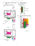
Page 14: ... Remove the VESA metal and Rear center cover 32 inch 26 inch 7 5 Control panel assy 1 Disconnect the connector A7 2 Remove the 2 screws 3 Remove the control panel assy 7 6 Side AV bracket and Inverter shield 1 Remove the side AV bracket All manuals and user guides at all guides com ...

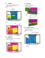
Page 15: ...1 Remove the 9 screws 2 Disconnect the connector A2 A3 A5 A7 A9 A16 3 Remove the A Board 7 9 V Board 1 Remove the 2 screws 2 Disconnect the connector V1 3 Remove the V Board 7 10 Chassis frame 1 Remove the 5 32 inch 4 26 inch screws C 2 Remove the 2 screws D 3 Remove the chassis frame 32 inch All manuals and user guides at all guides com ...

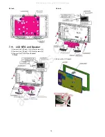
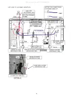
Page 16: ...eaker 1 Remove the 8 32 inch 6 26 inch screws G 2 Remove the 4 32 inch 2 26 inch screws H 3 Remove the LCD MTG and Speaker 32 inch 26 inch 4 Remove the LCD panel All manuals and user guides at all guides com a l l g u i d e s c o m ...

Page 17: ...17 7 12 EMI processing 32 inch All manuals and user guides at all guides com ...

Page 18: ...18 All manuals and user guides at all guides com ...

Page 19: ...19 All manuals and user guides at all guides com ...

Page 20: ...20 All manuals and user guides at all guides com ...

Page 21: ...21 7 13 EMI processing 26 inch All manuals and user guides at all guides com a l l g u i d e s c o m ...

Page 22: ...22 All manuals and user guides at all guides com ...

Page 23: ...23 All manuals and user guides at all guides com ...

Page 24: ... 83 0 09V SUB1 2V TP5601 1 26 0 06V SUB1 8V TP5602 1 83 0 09V SUB3 3V TP5600 3 3 0 16V Instrument Name Remarks 1 REMOTE TRANSMITTER 2 Ex Signal Standard signal Adjustment or Inspection Procedure Remarks procedure 1 Receive the RF standard signal Need standard sync signal Screen mode ZOOM or FULL Picture mode DYNAMIC AI OFF AI Picture OFF BACK LIGHT 30 Inspection 1 Enter Service mode and select MAI...

Page 25: ... set Pushing the remote controller OK key for about 3 seconds GAIN is suited to the adjustment value auto matically Instrument Name Remarks 1 REMOTE TRANSMITTER 2 Component Video signal generator 88 Color bar 100 White Adjustment or Inspection Procedure Remarks procedure 1 Receive 88 color bar 100 White ASPECT ZOOM or FULL Picture mode VIVID AI Picture OFF BACK LIGHT MAX VALUE Inspection 1 Enter S...

Page 26: ...26 All manuals and user guides at all guides com a l l g u i d e s c o m ...

Page 27: ...T DTV Audio signal SUB 5V DTV12V SENSE 3 3V DCDC SWITCH REMOTE STB 5V SUB 9V TS Serial SUB 9V Video front end Audio processor Micom HDMI Receiver AUDIO AMP SUB 3 3V COMP1 HUDSON2 SUB 1 8V A19 DCDC FOR FACTORY USED SUB 1 2V HDMI3 A10 SUB 1 8V Digital Video signal V Y C SUB 3 3V PANEL_ON L R DTV 12V PWM SEL FOR FACTORY USED HDMI2 Control Panel PANEL 12V A16 SOUND SOS LED DCDC 24V EEPROM L R INV SOS ...

Page 28: ...9 1 IC8300 12 8 1 IIC2 5 23 DIGITAL DEMODULATOR 16 22 A3 2 IC4004 13 IC5600 20 IIC V2_L BT_30V Norm Low Ab high EEPROM V SOUND_VCC TU8300 DTV 12V DET Digital Video signal V2_R 12V Digital Analog Tuner SUB 3 3V V2_V 22 Digital Audio signal L SUB 5V TV_SOS Analog Audio signal VIDEO2 SUB_5V R 12 14 IIC VIDEO1 VIDEO2 BT 30V SUB_5V IIC1 L Y PB PR 13 R L R STB5V 9V 3 3V D1_R V 8 5V IC7109 5V L R D1_Y P3...

Page 29: ...PANEL CURRENT 4 INV_SOS BACK LIGHT ADIM INV_PWM PICTURE CORRECT A14 INV_SOS IP CONVERTER FOR FACTORY USED A2 OSD MIX 20 A13 SCALING FOR FACTORY USED 31 DTV Decord MAIN MCU VIDEO SIGNAL PROCESSOR FOR FACTORY USED 27MHz A10 VIDEO PROCESS Control voltage FOR FACTORY USED AUIDO PROCESS 27MHz CH0 TS Serial SPDIF Digital Video signal A19 L A5 AUDIO AMP SPEAKER OUT 1 3 LVDS I F SPEAKER R SERIAL I F IC230...

Page 30: ...30 All manuals and user guides at all guides com ...

Page 31: ...nt Caution Please confirm that all flexible cables are assembled correctly Also make sure that they are locked in the connectors Verify by giving the flexible cables a very slight pull All manuals and user guides at all guides com a l l g u i d e s c o m ...

Page 32: ...32 10 2 Wiring 32 inch All manuals and user guides at all guides com ...

Page 33: ...33 10 3 Wiring 26 inch All manuals and user guides at all guides com ...

Page 34: ...34 All manuals and user guides at all guides com ...

Page 35: ...35 11 Schematic Diagram 11 1 Schematic Diagram Notes All manuals and user guides at all guides com ...

Page 36: ... 15 HO 16 HB C0DAEMZ00001 IC7101 C0DAEMZ00001 IC7001 P1 1 2 P7 1 2 3 4 5 6 7 8 9 L7042 EXCELDR35V L7043 EXCELDR35V T7001 ETS15AB136AH 2 NC 3 V1 6 P1 8 P2 14 NC 15 NC 4 V2 1 NC 9 S1 12 S2 13 NC T7002 G4DYA0000132 1 2 4 6 8 NC 9 10 11 12 13 14 15 16 K5D502BNA005 F7001 ZA7000 K4CZ01000027 ZA7004 K4CZ01000027 ZA7001 K4CZ01000027 ZA7005 K4CZ01000027 ZA7003 K4CZ01000027 CNC1S171R PC7000 PC7100 CNC1S171R...

Page 37: ...7052 TP7053 TP7054 TP7022 TP7050 TP7015 Q7009 2SD0601ASL Q7058 2SD0601ASL Q7022 2SB0709A0L JS7074 JS7062 JS7075 JS7066 JS7067 JS7068 JS7069 JS7013 R7120 22k R7112 22k R7135 10k R7069 37 4k 1 R7070 10k 1 R7061 47k 1 R7127 37 4k R7139 0 R7138 15k 1 R7126 7 15k R7152 470 1 2W R7103 47k R7121 33k R7111 63 4k 1 1 R7156 8 66k 1 R7155 1k R7110 10k 1 R7062 10k R7122 22k R7117 47k R7115 12k R7157 0 R7102 1...

Page 38: ...11 VDD12 IC8001 B4 VI1P12 IC8001 U17 VSS IC8001 V25 VSS IC8001 P25 VDDIO IC8001 W2 ED6 IC8001 U12 VDD12 IC8001 R14 VSS IC8001 G3 VI2ENB IC8001 AC2 XECS1 IC8001 N11 VSS IC8001 AE18 VSS IC8001 M1 SDA0 IC8001 B24 VDD33 IC8001 AF22 MMDQ22 IC8002 H9 DQ5 IC8001 W1 ED5 IC8001 AB24 MMMONA IC8001 E22 LVVDD IC8001 T3 EA3 IC8001 AD23 VSS IC8001 K16 VSS IC8002 D3 DQ11 IC8001 C4 VI1P13 IC8001 U13 VDD12 IC8001 ...

Page 39: ...TP8544 TP8513 TP8553 TP8501 TP8548 TP8516 TP8515 TP8517 TP8545 TP8551 TP8511 TP8547 TP8546 TP8510 TP8514 TP8500 TP8512 TP8552 EA2 SCL1 SBT2 SBO0 EA0 EA3 XECS5 XERE EA5 SCL0 EA4 XECS4 TDO SDCLK EA7 ESZ0 XEWE0 ESZ1 EA6 EA1 AG_DTV_XRST AD_SCL1 SMTSEL0 TDI AD_SCL3 SMTD0 NANDRYBY AG_SW_OFF_DET XRST SMTCLK0 TMS XIRQ1 SDWP AD_SCL2 XDCD0 TCK XIRQ3 TRST SBI0 VI2P29 VI2P17 MVDACO3 VI1CLK2 VI2P27 XECS3 SDCMD...

Page 40: ...3 VCC 24 OUT1 2 25 LX1 26 OUT1 1 27 CB1 28 PGOOD 29 CUVP 30 OVP A3 1 2 3 4 5 6 7 8 9 10 11 12 13 14 15 16 17 18 19 20 21 22 23 L4704 J0JHC0000078 L4703 J0JHC0000078 L5605 J0JHC0000075 L4702 J0JHC0000078 L5602 G1C4R7Z00014 L5601 G1C2R2Z00007 L7006 G1C100MA0203 L7007 G1C6R3ZA0156 L5606 G1C100MA0077 L5600 G1C2R2Z00007 L5604 G1C100MA0203 STB3 3V DTV12V SUB9V STB5V SUB5V STB1 8V STB5V STB5V DTV12V BT30...

Page 41: ...002916 IC2301 1 IN1 44 IN2 2 PLMT1 3 PLMT2 4 PLMT3 5 PLMT4 6 BSP1P 7 VCCP1P 8 VCCP1P 9 OUT1P 10 OUT1P 11 GNDP1 12 GNDP1 13 OUT1N 14 OUT1N 15 VCCP1N 16 VCCP1N 17 BSP1N 18 WARNING 19 ERROR 20 MUTEX 21 N C 22 N C 23 OSC 24 MS 25 ROSC 26 TM 27 VHOLD 28 BSP2N 29 VCCP2N 30 VCCP2N 31 OUT2N 32 OUT2N 33 GNDP2 34 GNDP2 35 OUT2P 36 OUT2P 37 VCCP2P 38 VCCP2P 39 BSP2P 40 VCCA 41 FILP 42 FILA 43 GNDA C2309 TP23...

Page 42: ... 20 R4120 22 1 R4046 20 R4006 10k R4069 22 R4059 220 R4110 10k 1 R4035 22k R4068 22 R4066 75 1 R4037 20 R4107 47k R4060 1k R4001 10k R4081 47k R4011 100 R4065 1k R4159 0 1 R4050 57 6 R4126 47k R4139 10k 1 R4049 10k R4056 1k R4091 47k R8734 33 R4062 2 2k R4012 470k 47k R4092 1 R4042 20 R4098 47k R4114 68 R4076 22 R4155 56k R4151 22k R4025 10k R4115 68 330 R4148 R4113 68 R4078 22 1 R4036 22k R8731 6...

Page 43: ...CL3 3 GND 4 B31 5 A31 6 VCC 7 B32 8 A32 9 GND 10 B33 11 A33 12 VCC 13 B34 14 A34 15 GND 16 VSADJ 17 Y4 18 Z4 19 VCC 20 Y3 21 Z3 22 GND 23 Y2 24 Z2 25 VCC 26 Y1 27 Z1 28 GND 29 SCL_SINK 30 SDA_SINK 31 HPD_SINK 32 S1 33 S2 34 EQ 35 HPD1 36 SDA1 37 SCL1 38 B11 39 A11 40 VCC 41 B12 42 A12 43 GND 44 B13 45 A13 46 VCC 47 B14 48 A14 49 VDD 50 HPD2 51 SDA2 52 SCL2 53 B21 54 A21 55 VCC 56 B22 57 A22 58 GND...

Page 44: ...8 VSS3 49 IBAGCIF 50 VDDL3 51 IBAGCRF 52 VSS4 53 GPIO2 54 SADR1 55 VSS5 56 NRST 57 VDDL4 58 GPIO3 59 VSS6 60 GPIO4 61 VDDH1 62 GPIO5 63 VSS7 64 GPIO6 65 VDDL5 66 GPIO7 67 FIXL0 68 VSS8 69 FIXL1 70 FIXL2 71 FIXL3 72 NC12 73 NC13 74 NC14 75 VDDL6 76 IBFSYNC 77 IBERR 78 OPN1 79 VSS9 80 VDDH2 81 OPN2 82 OPN3 83 VSS10 84 VDDL7 85 OPN4 86 OPN5 87 VSS11 88 VDDH3 89 OPN6 90 OPN7 91 VSS12 92 VDDH4 93 IBPCK...

Page 45: ...4716 0 JS3077 0 Q4305 2SC39380QL R4357 10k FL2615 J0JAD0000028 1 2 3 4 TP2608 MVCLK R4350 22 TP1221 TP1222 C2694 16V 47u R4305 47k IS0DATA TB1N R4326 10 Q4304 2SD0601A0L J0HAYY000011 FL4034 1 2 3 4 TE1N TP2607 PNL12V TP1223 1 R4365 6 04k TB1P C2693 16V 0 01u TA1P TP2602 TP2605 J0HAYY000011 FL4035 1 2 3 4 R4362 10k TCLK1P R4361 10k 22 R8116 MHQICTRL9V TC1N TP2609 R4356 10k TC1P C4406 47u 16V TP2603...

Page 46: ...3 D7014 D7015 D7016 D7017 RL7005 C7044 RL7012 PC7000 C7050 C7051 C7057 D7035 D7036 D7037 Q7058 D7039 Q7059 C7060 Q7060 D7040 D7042 D7043 D7045 R7043 R7048 T7001 R7049 R7050 R7053 R7054 D7058 R7059 D7062 R7060 C7088 D7064 R7061 C7089 R7062 D7066 D7067 D7069 R7069 R7070 C7099 D7077 D7084 D7085 D7086 D7087 D7088 D7090 D7091 D7092 D7093 R7090 D7094 D7095 R7091 D7096 D7097 D7098 R7094 D7099 R7095 R7096...

Page 47: ... J103 J104 J105 J106 J107 J108 J109 J301 J302 J303 R7090 D7094 J110 J304 D7095 J111 J305 D7096 J112 J306 D7097 J113 J307 D7098 J114 J308 D7099 J309 J117 J119 J310 J311 J312 J313 CF7000 J314 J121 J315 J316 J123 HOT 12 3 4 4 3 2 1 CAUTION FOR CONTINUED PROTECTION AGAINST RISK OF FIRE REPLACE ONLY WITH Littel fuse TYPE 215 4 1 3 2 32 only 1 2 1 2 SOUND_VCC BT30V 5VS SUB5V SUB9V DTV12V PANEL_12V 1 2 3...

Page 48: ...4639 C2127 C2308 C4040 R4000 C4005 L5605 C4797 C8014 C7056 R4140 D4711 C4108 R8518 L8006 R5626 R5618 R4089 C4084 C4077 R4044 TP8547 R8091 C4008 R8034 C8016 C4754 D4713 R4128 C4724 TP3017 C8372 R8337 R8106 C5631 D5604 C5621 C4093 TP1221 R4023 C4047 R8038 X8300 C7059 R4129 C4725 CL8002 R8723 L8009 JS4001 C5634 R4649 TP4102 R8099 R8095 C8061 R8025 R8004 C8003 R4151 R4528 R4121 C4528 C4517 TP3019 R563...

Page 49: ...2 R4074 R8325 C8376 C4119 R3005 IC8002 R4715 R4512 D7009 R4503 C4716 R2110 R2109 IC4008 D3815 C4088 C8343 TU8300 A C5766 A15 R3008 L2313 R4541 R4147 R8579 C4718 R2111 C4072 C4026 R8512 C8359 R8548 R8021 FL4703 R4164 C4701 L4701 R4080 JK4501 JS3078 R8539 C4787 C4128 C4069 C4606 R4082 JK4500 R8017 D4502 R4103 C2332 C4409 R4640 R8308 IC8503 R3004 R8591 D4503 R8070 R4641 C8503 D5605 R4093 C8374 C4118 ...

Page 50: ...50 All manuals and user guides at all guides com ...

Page 51: ...51 13 Exploded View and Replacement Parts List 13 1 Exploded View and Mechanical Replacement Parts List 13 1 1 Exploded View All manuals and user guides at all guides com a l l g u i d e s c o m ...

Page 52: ...52 13 1 2 Mechanical Replacement Parts List All manuals and user guides at all guides com ...

Page 53: ...TKR2AA00211 SD DOOR 1 PAVCA 15 TKX2AA0331 PEDESTAL COVER 1 PAVCA TMM25401 CLAMPER 10 TMM6428 1 CLAMPER 2 TMME047 CLAMPER 2 TMME111 CLAMPER 2 TMME287 CLAMPER 3 11 TMW2AX0301 LED BRACKET 1 PAVCA 12 TQB2AA0774 INSTRUCTION BOOK ENG SPA FRENCH 1 PAVCA 9 TXFKP01TSER SIDE AV BRACKET 1 PAVCA 13 TXFKU01TSER REAR COVER 1 PAVCA TC 26LX85 13 TXFKU07TSER REAR COVER 1 PAVCA TC 32LX85 14 TXFKY01TSER CABINET ASSY...

Page 54: ...54 13 2 Electrical Replacement Parts List 13 2 1 Replacement Parts List Notes All manuals and user guides at all guides com ...
Page 55: ...2335 F1H1E104A129 E 0 1UF 25V 1 TC 32LX85 C2335 ECJ1XB1C473K C 0 047UF Z 16V 1 TC 26LX85 C2337 ECJ1XB1H104K C 10PF J 50V 1 C2338 EEEHB1C100R C 10PF J 16V 1 C2339 F1J1C684A097 C 0 68UF Z 16V 1 C2340 42 ECJ1XB1H104K C 10PF J 50V 3 C2344 ECJ1VB1C105K C 0 01UF K 16V 1 C2692 93 ECJ0EB1C103K C 0 010UF K 16V 2 C2694 F2G1C4700052 E 47UF 16V 1 C3177 F1H1A1050032 E 10UF 50V 1 C4000 F1H1H102A971 C 1000PF K 5...

Page 56: ... Description Pcs Remarks C4761 63 F1H1H103A970 C 0 001UF K 50V 3 C4771 F1G1H102A730 E 1000UF 50V 1 C4772 F1G1C104A116 C 0 10UF K 16V 1 C4773 F1G1H102A730 E 1000UF 50V 1 C4775 F1G1C104A116 C 0 10UF K 16V 1 C4776 F1G1H102A730 E 1000UF 50V 1 C4778 81 F1G1C104A116 C 0 10UF K 16V 4 C4782 F1G1H102A730 E 1000UF 50V 1 C4785 87 F1G1H102A730 E 1000UF 50V 3 C4795 98 F1G1H102A730 E 1000UF 50V 4 C5600 F1H1A105...

Page 57: ...51 F1G1C104A116 C 0 10UF K 16V 9 C8052 F1H0J1050012 C 1UF K 16V 1 C8053 ECJ0EB1C103K C 0 010UF K 16V 1 Safety Ref No Part No Part Name Description Pcs Remarks C8056 57 F1G1C104A116 C 0 10UF K 16V 2 C8058 F1J1A106A043 C 0 010UF K 10V 1 C8067 ECJ0EB1C103K C 0 010UF K 16V 1 C8068 F1G1C104A116 C 0 10UF K 16V 1 C8069 F1G1H820A731 E 82UF 50V 1 C8070 74 F1G1C104A116 C 0 10UF K 16V 5 C8075 F1J0G2260001 C ...

Page 58: ...DE 3 D7105 MAZ82700ML ZENER DIODE 1 D7106 MA2J11100L DIODE 1 D7107 MA8240MTX ZENER DIODE 1 D7108 B0JAPK000011 DIODE 1 D7109 MAZ81500ML ZENER DIODE 1 Safety Ref No Part No Part Name Description Pcs Remarks D7112 B0JAPK000011 DIODE 1 D7115 B0JAPK000011 DIODE 1 D7124 B0JBSL000024 DIODE 1 PAVCA D7130 31 B0HCMM000014 DIODE 2 F7001 1 K3GE1ZA00010 FUSE HOLDER 1 F7001 2 K3GE1ZA00010 FUSE HOLDER 1 F7001 K5...

Page 59: ...1 03 2SD0601ARL TRANSISTOR 3 Q2104 05 2SB0709ARL TRANSISTOR 2 Q2106 2SD0601ARL TRANSISTOR 1 Q2201 02 2SD0601ARL TRANSISTOR 2 Safety Ref No Part No Part Name Description Pcs Remarks Q2203 B1ADCE000022 TRANSISTOR 1 Q2350 2SD0601ARL TRANSISTOR 1 Q4000 2SB0709ARL TRANSISTOR 1 Q4003 05 2SD0601ARL TRANSISTOR 3 Q4007 2SD0601ARL TRANSISTOR 1 Q4302 2SD0601ARL TRANSISTOR 1 Q4303 B1ADCE000022 TRANSISTOR 1 Q4...

Page 60: ...2GEJ102X M 1KOHM J 0 063W 1 R4057 ERJ2GEJ221 M 220 OHM J 0 063W 1 R4058 ERJ2GEJ473 M 47KOHM J 0 063W 1 Safety Ref No Part No Part Name Description Pcs Remarks R4059 ERJ2GEJ221 M 220 OHM J 0 063W 1 R4060 ERJ2GEJ102X M 1KOHM J 0 063W 1 R4061 ERJ2GEJ220 M 22 OHM J 0 063W 1 R4062 ERJ2GEJ222 M 2 2KOHM J 0 063W 1 R4064 ERJ2RKF2490X M 249 OHM 0 063W 1 PAVCA R4065 ERJ2GEJ102X M 1KOHM J 0 063W 1 R4066 ERJ2...

Page 61: ...escription Pcs Remarks R4540 ERJ2GEJ473 M 47KOHM J 0 063W 1 R4541 43 ERJ2GEJ680 M 68 OHM J 0 063W 3 R4552 ERJ2GEJ220 M 22 OHM J 0 063W 1 R4561 ERJ2GEJ473 M 47KOHM J 0 063W 1 R4564 65 ERJ2GEJ220 M 22 OHM J 0 063W 2 R4567 D1BB4641A055 M4 64KOHM 1 10W 1 PAVCA R4570 D1BB3832A055 M38 3KOHM 1 10W 1 PAVCA R4571 D1BB2202A055 M 22KOHM 1 10W 1 PAVCA R4572 ERJ2GEJ472 M 4 7KOHM J 0 063W 1 R4600 ERJ2GEJ103 M 1...

Page 62: ...HM J 1 10W 2 R7105 ERJ14YJ222 M 22KOHM J 1 4W 1 R7108 09 ERJ6GEYJ224 M 220KOHM J 1 10W 2 R7110 D1BD1002A044 M10 0KOHM 1 10W 1 PAVCA R7111 ERJ6ENF6342 M6 34KOHM 1 10W 1 R7112 ERJ6GEYJ223 M 22KOHM J 1 10W 1 R7113 ERG2SJ563P M 56KOHM J 2W 1 PAVCA R7114 D0GDR00Z0002 M 0 OHM 1 10W 1 R7115 ERJ6GEYF123 M 12KOHM J 1 10W 1 R7116 ERJ12YJ2R2 M 2 2 OHM J 1 2W 1 R7117 ERJ6GEYF473 M 47KOHM J 1 10W 1 R7118 ERX12...

Page 63: ...o Part No Part Name Description Pcs Remarks R8505 07 D1HG5608A002 NETWORK RESISTER 3 R8508 EXB2HV473JV RESISTOR ARRAY 1 R8509 10 D1HG5608A002 NETWORK RESISTER 2 R8512 ERJ2GEJ103 M 10KOHM J 0 063W 1 R8517 ERJ2RKD330 M 33 OHM J 0 063W 1 R8519 20 ERJ2RKD330 M 33 OHM J 0 063W 2 R8528 30 ERJ2GEJ560 M 56 OHM J 0 063W 3 R8532 ERJ2GEJ560 M 56 OHM J 0 063W 1 R8540 45 ERJ2GEJ220 M 22 OHM J 0 063W 6 R8546 48...

Page 64: ...ABS CIRCUIT BOARD A 1 PAVCA TC 26LX85 TXN P10NGCS CIRCUIT BOARD P 1 PAVCA TNPA4483S CIRCUIT BOARD V 1 PAVCA T7001 ETS15AB136AH SWITCHING TRANS FORMER 1 T7002 G4DYA0000132 SWITCHING TRANS 1 PAVCA Safety Ref No Part No Part Name Description Pcs Remarks All manuals and user guides at all guides com ...
Reviews: