26
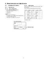
8.2.
Adjustment
8.2.1.
White balance adjustment
Name of measuring instrument
Connection
Remarks
• W/B pattern
• Color analyzer
(Minolta CA-100 or equivalent)
Component input
Panel surface
Procedure
Remarks
• Make sure the front panel to be used on the final set is fitted.
• Make sure a color signal is not being shown before adjustment.
• Put the color analyzer where there is little color variation.
1. Output a white balance pattern.
2. Check that the color temperature is [Cool].
3. Set to serviceman mode, WB-ADJ.
4. Set [R-CUT] [G-CUT] [B-CUT] the values written in table 1.
5. Attach the sensor of color analyzer to the center of highlight window.
6. Fix G drive at C0h and adjust [B-DRV] and [R-DRV] so x, y value of color analyzer
become the [Color temperature High] in table 2.
7. Increase RGB together so the maximum drive value in RGB becomes FC. That is,
set [ALL DRIVE] to FC.
Execute adjustment again. When that, the maximum value of R/G/B DRV should be FC,
and either R/G/B DRV should be FC.
8. Set color temperature to [Normal].
9. Set [R-CUT] [G-CUT] [B-CUT] the values written in table 1.
10. Attach the sensor of color analyzer to the center of highlight window.
11. Fix G drive at C0h and adjust [B-DRV] and [R-DRV] so x, y value of color analyzer
become the [Color temperature Mid] in table 2.
12. Increase RGB together so the maximum drive value in RGB becomes FC. That is,
set [ALL DRIVE] to FC.
Execute adjustment again. When that, the maximum value of R/G/B DRV should be FC,
and either R/G/B DRV should be FC.
13. Set color temperature to [Warm].
14. Set [R-CUT] [G-CUT] [B-CUT] the values written in table 1.
15. Attach the sensor of color analyzer to the center of highlight window.
16. Fix G drive at C0h and adjust [B-DRV] and [R-DRV] so x, y value of color analyzer
become the [Color temperature Low] in table 2.
17. Increase RGB together so the maximum drive value in RGB becomes FC. That is,
set [ALL DRIVE] to FC.
Execute adjustment again. When that, the maximum value of R/G/B DRV should be FC,
and either R/G/B DRV should be FC.
18. Set color temperature to [Cool].
- adjustment of [Normal] [Warm] by data shift from [Cool] adjust. -
For [Normal] [Warm] adjustment, set values that the adjusted value of [Cool]
plus the figures wrote below.
When the measurement data is not in the following tolerance by the shipping confirma-
tion, please re-adjust.
Tolerance : ( x , y ) = ( setting data±0.007, setting data±0.007)
19. Copy values adjusted by HD pattern to the NTSC data area of EEPROM.
Summary of Contents for Viera TH-50PE8U
Page 15: ...15 6 4 No Picture ...
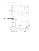
Page 25: ...25 8 1 4 Adjustment Volume Location 8 1 5 Test Point Location ...
Page 27: ...27 ...
Page 28: ...28 ...
Page 34: ...34 ...
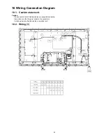
Page 36: ...36 10 3 Wiring 2 ...
Page 37: ...37 11 Schematic Diagram 11 1 Schematic Diagram Note ...
Page 94: ...94 13 1 2 Accessories ...
Page 95: ...95 13 1 3 Mechanical Replacement Parts List ...
Page 98: ...98 13 2 Electrical Replacement Parts List 13 2 1 Replacement Parts List Notes ...


