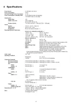
4 Specifications
Power Source
Power Consumption
On mode Average Power Consumption
Power Consumption in Standby mode
Display panel
Aspect Ratio
Visible screen size
Number of pixels
Sound
Speaker
Audio Output
Headphones
Receiving Systems / Band name
Aerial - input
Operating Conditions
Connection Terminals
AV1 (Scart terminal)
AV2 (Scart terminal)
AV3
VIDEO
AUDIO L - R
COMPONENT
VIDEO
AUDIO L - R
Others
HDMI1 / 2 / 3
Card slot
Output
AUDIO L - R
DIGITAL AUDIO OUT
Dimensions (W
x
H
x
D)
Mass
AC 220-240 V, 50 / 60 Hz
275 W
117 W
0.4 W (W ithout m onitor out recording)
15 W (With m onitor out recording)
16:9
106 cm (diagonal)
921 mm (W)
x
518 mm (H)
2,073,600 (1,920 (W)
x
1,080 (H)) [5,760
x
1,080 dots]
160 mm
x
40 mm
x
2 pcs, 6
Q
20 W ( 10 W + 10 W )
M3 (3.5 mm) stereo mini Jack
x
1
PAL B, G, H, I, SECAM B, G, SECAM L, L’
VHF E2 - E12
VHF A - H (ITALY)
CATV (S01 - S05)
CATV S11 - S20 (U1 - U10)
PAL D, K, SECAM D, K
VHF R1 - R2
VHF R6 - R12
PAL 525/60
M.NTSC
NTSC (AV input only)
DVB-T
DVB-C
VHF H1 - H2 (ITALY)
UHF E21 - E69
CATV S1 - S10 (M1 - M10)
CATV S21 - S41 (Hyperband)
VHF R3 - R5
UHF E21 - E69
Playback o f NTSC tape from some PAL Video recorders (VCR)
Playback from M. NTSC Video recorders (VCR)
Playback from NTSC Video recorders (VCR)
Digital terrestrial services (M PEG 2 and M PEG 4-AVC(H.264))
Digital cable services (M PEG 2 and M PEG 4-AVC(H.264))
C ountries that DVB-C is available: Germany, Switzerland,
Denmark, Sweden, Norway, Finland, N etherlands
• Check the latest inform ation on the available services at the following website. (English only)
http://panasonic.jp/support/global/cs/
V H F / UHF
Temperature:
Humidity:
0 °C - 35 °C
20 % - 80 % RH (non-condensing)
21 Pin term inal (Audio/Video in, Audio/Video out, RGB in, Q-Link)
21 Pin term inal (Audio/Video in, Audio/Video out, RGB in, S-Video in, Q-Link)
RCA PIN Type
x
1
RCA PIN Type
x
2
1.0 V [p-p] (75 Q)
0.5 V [rms]
Y
P
b
, P
r
RCA PIN Type
x
2
1.0 V [p-p] (including synchronization)
± 0.35 V [p-p]
0.5 V [rms]
TYPE A Connectors
HDMI1 / 3 :
HDMI (Version 1.3a with x.v. Colour.)
HDMI2 :
HDMI (Version 1.4 with Audio Return Channel) and
HDMI (Version 1.3a with x.v. Colour.)
•
T his TV supports [ HDAVI Control 5 ] function.
SD Card slot
x
1
Com mon Interface slot
x
1
RCA PIN Type
x
2
0.5 V [rms] (high im pedance)
PCM / Dolby Digital / DTS, Fiber optic
1.029 mm
x
704 mm
x
334 mm (With Pedestal)
1.029 mm
x
661 mm
x
93 mm (TV only)
24.5 kg Net (With Pedestal)
23.0 kg Net (TV only)
8
Summary of Contents for Viera TX-P42S20L
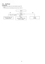
Page 21: ...7 4 No Picture 21...
Page 33: ...11 Block Diagram 11 1 Main Block Diagram 33...
Page 34: ...11 2 Block 1 4 Diagram 34...
Page 35: ...G 0 11 3 Block 2 4 Diagram I A I D IG IT A L S IG N A L P R O C E S S O R 35...
Page 36: ...11 4 Block 3 4 Diagram P P O W E R S U P P LY 36...
Page 37: ...11 5 Block 4 4 Diagram s c s c a n d r i v e s s s u s t a i n d r i v e 37...
Page 38: ...38...
Page 40: ...12 3 Wiring 2 40...
Page 43: ...13 2 P Board 1 4 Schematic Diagram A B C D E A P BO ARD LSEP1287BE HB 1 4 F 1 2 3 4 42...
Page 44: ...13 3 P Board 2 4 Schematic Diagram A P BO ARD LSEP1287BE HB 2 4 10 11 12 13 14 15 16 17 18 43...
Page 45: ...13 4 P Board 3 4 Schematic Diagram A B C D E F 1 2 3 4 44 5...
Page 46: ...13 5 P Board 4 4 Schematic Diagram 10 11 12 13 14 15 16 17 18 45...
Page 47: ...13 6 A Board 1 19 Schematic Diagram A A A BO AR D 1 19 IIC B C D E F 1 2 3 4 9 46...
Page 52: ...13 11 Board 6 19 Schematic Diagram A A BO AR D 6 19 STB MPU 46 47 48 49...
Page 54: ...13 12 Board 7 19 Schematic Diagram A A BO AR D 7 1 9 HDMI 55 56 57 58 59 52...
Page 57: ...69 70 71 72...
Page 59: ...Peaks COM MON 78 79 80 81...
Page 61: ...13 16 A Board 11 19 Schematic Diagram A A BO AR D 11 19 A V SW 91 92 93 94 95 96 97 98 99 56...
Page 63: ...FE_Virtual_Module Peaks COMMON TO 3 19 Analog ASIC 104 105 106 107 108 57...
Page 68: ...140 141 142 143 144 61...
Page 71: ...63...
Page 72: ...13 24 A Board 19 19 Schematic Diagram A A BO AR D 19 19 DVB T C D EM O D U LATO R 64...
Page 75: ...13 27 C2 Board 1 2 Schematic Diagram A A C 2 BO AR D TN PA5095 1 2 ___ I TO A BOARD A32 B 67...
Page 78: ...13 30 SC Board 2 4 Schematic Diagram 10 I 11 1 12 1 13 1 14 1 15 1 16 1 17 1 18 70...
Page 79: ...13 31 SC Board 3 4 Schematic Diagram 19 1 20 1 21 1 22 1 23 1 24 1 25 1 26 1 27 71...
Page 80: ...13 32 SC Board 4 4 Schematic Diagram 28 29 30 31 32 33 34 35 36 72...
Page 86: ...P BOARD COMPONENT SIDE LSEP1287BEHB B G 6 5 4 3 2 1 E F H 77...
Page 92: ...14 6 SC Board SC BOARD FOIL SIDE TXNSC11DEK B G 6 5 4 3 2 1 E F H 83...
Page 93: ...SC BOARD COMPONENT SIDE TXNSC11DEK B G 6 5 4 3 2 1 E F H 84...
Page 94: ...14 7 SS Board SS BOARD FOIL SIDE TXNSS11DEK B G 6 5 4 3 2 1 E F H 85...
Page 95: ...SS BOARD COMPONENT SIDE TXNSS11DEK...
Page 96: ......
Page 98: ...15 1 2 Exploded View 2 88...
Page 99: ...15 1 3 Packing 1 89...
Page 100: ...15 1 4 Packing 2 90...


