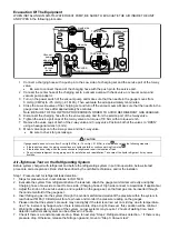
2. Set the Pressure Relief Valve
13
level “DOWN”.
Pressure relief
valve
Lever
Turn up
Pressure relief valve
13
13
3. Start filling water (with pressure more than 0.1
MPa (1 bar)) to the Indoor Unit via water inlet.
Stop filling water if the free water flow through
Pressure Relief Valve drain hose.
4. Turn ON the power supply and make sure Water
Pump
16
is running.
5. Check and make sure no water leaking at the tube
connecting points.
Reconfirmation
WARNING
Be sure to switch off all power supply before performing each of the
below checkings. Before obtaining access to terminals, all supply
circuits must be disconnected.
Check Water Pressure
*(0.1 MPa = 1 bar)
Water pressure should not lower than 0.05 MPa (with
inspects the Water Pressure Gauge
14
). If necessary
add tap water into Tank Unit. Refer to Tank unit
installation instruction for details on how to add water.
Check Pressure Relief Valve
13
Check for correct operation of Pressure Relief
Valve
13
by turning on the lever to become
horizontal.
If you do not hear a clacking sound (due to water
drainage), contact your local authorized dealer.
Push down the lever after finish checking.
In case the water keeps drained out from the unit,
switch off the system, and then contact your local
authorized dealer.
Check RCCB/ELCB
Ensure the RCCB/ELCB set to “ON” condition before
check RCCB/ ELCB.
Turn on the power supply to the Indoor Unit.
This testing could only be done when power is
supplied to the Indoor Unit.
WARNING
Be careful not to touch parts other than RCCB/ELCB test button
when the power is supplied to Indoor Unit. Else, electrical shock
may happen. Before obtaining access to terminals, all supply
circuits must be disconnected.
Push the “TEST” button on the RCCB/ELCB. The
lever would turn down and indicate “0”, if it
functions normal.
Contact authorized dealer if the RCCB/ELCB
malfunction.
Turn off the power supply to the Indoor Unit.
If RCCB/ELCB functions normal, set the lever to
“ON” again after testing finish.
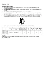
This product contains fluorinated greenhouse gasses.
Refrigerant type: R410A (GWP=2088)
Amount: For SXC09*3E8/SXC12*9E8 2.85 kg (5.9508
ton CO
2
equivalent)
For SXC16*9E8 2.90 kg (6.0552 ton CO
2
equivalent)
For SDC09*3E8/SDC12*9E8/SDC16*9E8
2.55kg (5.3244 ton CO
2
equivalent)
(The amount do not include the additional refrigerant
when refrigerating piping length extended. Please
refer to adhered label on outdoor unit for exact
amount of refrigerant used and actual tonnes of CO
2
equivalent.)
Test Run
1. Fill up the Tank Unit with water. For details refer to
Tank Unit installation instruction and operation
instruction.
2. Set ON to the Indoor Unit and RCCB/ELCB. Then,
for control panel operation please refers to air-to-
water heatpump operation instruction.
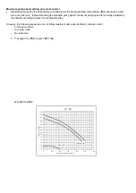
3. For normal operation, pressure gauge
14
reading
should be in between 0.05 MPa and 0.3 MPa.
4. After test run, please clean the Water Filter Set
15
.
Reinstall it after finish cleaning.
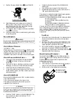
Reset Overload Protector
11
Overload Protector
11
serves the safety purpose to
prevent the water over heating. When the Overload
Protector
11
trip at high water temperature, take
below steps to reset it.
1. Take out the cover.
2. Use a test pen to push the centre button gently in
order to reset the Overload Protector
11
.
3. Fix the cover to the original fixing condition.
Use test pen to push
this button for reset
Overload protector .
11


