


15
10 Installation Instruction
10.1. Select The Best Location
• Install the Tank Unit in indoor only.
• Must install on a flat horizontal and solid hard surface.
• There should not be any heat source or steam near the Tank
Unit.
• A place where air circulation in the room is good.
• A place where drainage can be easily done (e.g. Utility
room).
• A place where Tank Unit’s operation noise will not cause
discomfort to the user.
• A place where Tank Unit is far from door way.
• A place where accessible for maintenance.
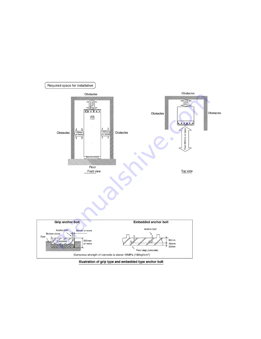
• Ensure to keep minimum distance of spaces as illustrated
below from wall, ceiling, or other obstacles.
• A place where flammable gas leaking might not occur.
10.2. Tank Unit Installation
Tank Unit will become heavy when filled with water. Therefore, please install the Tank Unit on strong concrete floor, by considering
weight of unit and water.
• Fix Tank Unit on the concrete floor with M12 anchor bolt at 4 locations.
• Pull-out strength of these anchor bolts must be above 15000N.
Summary of Contents for WH-TX30B9E8
Page 7: ...7 4 Location of Controls and Components 4 1 Tank Unit 4 1 1 Location of Control ...
Page 8: ...8 4 1 2 Main Components ...
Page 9: ...9 5 Dimensions ...
Page 10: ...10 6 Water Cycle Diagram ...
Page 11: ...11 7 Wiring Connection Diagram ...
Page 12: ...12 8 Electronic Circuit Diagram 8 1 Indoor Unit ...
Page 13: ...13 9 Printed Circuit Board 9 1 Tank Unit 9 1 1 Main Printed Circuit Board ...
Page 14: ...14 9 1 2 Surge Printed Circuit Board ...
Page 47: ...47 15 2 Heater Removal Procedures ...
Page 48: ...48 15 3 Main Printed Board Removal Procedures ...
Page 49: ...49 15 4 Control Board Removal Procedure ...
Page 50: ...50 15 5 Pressure Relief Valve Procedures ...
Page 51: ...51 15 6 Flow Switch Removal Procedures 15 7 Water Pump Removal Procedures ...
Page 52: ...52 16 Technical Data 16 1 Pump Characteristic 16 2 Water Tank Sensor Characteristic ...
Page 53: ...53 ...
Page 54: ...54 ...


