


20
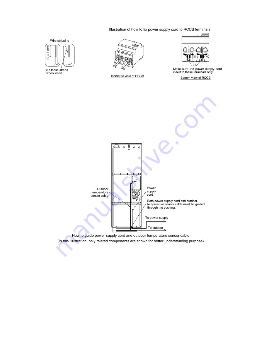
Wire Stripping And Connecting Requirement
Guiding Outdoor Temperature Sensor Cable
1. Guide the outdoor temperature sensor cable inside the Tank Unit as illustrated below.
2. To avoid cable damaged by sharp edge, the cable must be guided through Bushing. The bushing must be used and must not
be removed.
3. The sensor must be located in the most suitable place, such as on a wall of house facing north-west or north to avoid
exposure to the morning sunlight. The reading of sensor might be affected by the heat radiated from direct sunlight.
4. The sensor must be placed at level of about 2/3 height of the wall.
5. Do not to place the sensor over the ventilation ducts, doors, windows or area where might be affected by other temperature
instead of outdoor temperature.
6. Avoid guiding of the cable through sharp edges and high temperature parts. Fail to do so might cause the cable damage.
Summary of Contents for WH-TX30B9E8
Page 7: ...7 4 Location of Controls and Components 4 1 Tank Unit 4 1 1 Location of Control ...
Page 8: ...8 4 1 2 Main Components ...
Page 9: ...9 5 Dimensions ...
Page 10: ...10 6 Water Cycle Diagram ...
Page 11: ...11 7 Wiring Connection Diagram ...
Page 12: ...12 8 Electronic Circuit Diagram 8 1 Indoor Unit ...
Page 13: ...13 9 Printed Circuit Board 9 1 Tank Unit 9 1 1 Main Printed Circuit Board ...
Page 14: ...14 9 1 2 Surge Printed Circuit Board ...
Page 47: ...47 15 2 Heater Removal Procedures ...
Page 48: ...48 15 3 Main Printed Board Removal Procedures ...
Page 49: ...49 15 4 Control Board Removal Procedure ...
Page 50: ...50 15 5 Pressure Relief Valve Procedures ...
Page 51: ...51 15 6 Flow Switch Removal Procedures 15 7 Water Pump Removal Procedures ...
Page 52: ...52 16 Technical Data 16 1 Pump Characteristic 16 2 Water Tank Sensor Characteristic ...
Page 53: ...53 ...
Page 54: ...54 ...


