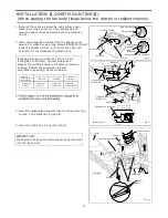
7. Finish ceiling work. Ceiling hole should be aligned
with the edge of the flange. (Fig.5)
8. Insert the plug connector
into the receptacle ,
and secure the lighting unit to the fan
body with 1 screw
(ST4.2X16) and 2 machine
screws (M4X8). (Fig.5)
II
II
III
9. Insert the fluorescent lamps and secure the night
lamp into the lighting unit . (Fig.5)
10. Insert mounting spring into the slot as shown and
adjust high/low delay time preset switch and low
speed air volume preset switch. Refer to switch
indication on page 5 (FV-08VKML2) (Fig.6-1)
11. Insert the sensor unit into the housing of the grille
and insert other mounting spring into the slot as
shown and mount grille to fan body (FV-08VKML2)
(Fig.6-2, Fig.6-3)
12. Insert mounting springs into the slots as shown and
mount grille to fan body. (FV-08VKSL2) (Fig.7)
Mount grille carefully so that lead wire of sensor unit
is not pinched.
CAUTION:
INSTALLATION (JOIST MOUNTING- ) CONTINUED
Ceiling
Lighting unit
Machine screw
(M4X8)
Machine screw
(M4X8)
Screw
(ST4.2X16)
III
4 W Night lamp
Fluorescent lamps
Inches (mm)
Plug connector
II
Mounting spring
Mounting spring
Ceiling
Ceiling
Ceiling
Ceiling
Grille
Grille
Grille
Gloves
Grille
Slot
Lighting unit
Lighting unit
Sensor unit
Sensor unit
Fig.5
Fig.6-1
Fig.6-2
Fig.6-3
Fig.7
Gloves
10
Receptacle
II
Plug connector
II
Gloves
Gloves
The machine screws must be tight fit.
CAUTION:
PDF created with pdfFactory Pro trial version
www.pdffactory.com

