background image

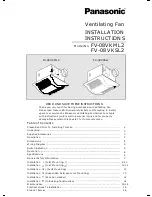
PLEASE READ PRIOR TO INSTALLING THIS FAN

The WhisperGreen line of ventilating fans employs state of the art technology

providing a number of unique features that lead to improved indoor air quality.
These features need to be fully understood prior to installation to fully realize the
benefits the fans offer.

These fans are designed to run continuously

ensuring a healthy environment at low CFM levels 24 hours a day.By utilizing

a pre-set lower level(0,30,40,50,60,70 CFM).The setting is dependent on the

size of the room and the individual wishes of the homeowner.

(

Sq.feet)

Two Bedrooms Three Bedrooms Four Bedrooms Five Bedrooms

<

1,000

33

40

48

55
60

53

45

38

1,500
2,000

43

50

58

65
70

63

55

48

2,500
3,000

53

60

68

These fans are also built to take care of the homeowner's spot ventilation needs

when the room is occupied.These models kick-up to a maximum level of 80
CFM either when the switch is turned on(FV-08VKSL2)or activated by the

A High/Low Delay Timer,Iocated inside the fan body, is utilized to return the fan
back to the Pre-set continuous ventilation mode

.

factors increase static pressure hindering the performance of most ventilation

fans.These fans utilize

microchip technology that monitors the

static pressure in the system and speeds up or slows down the rpm of the fan

depending on the amount of resistance.This allows the fan to perform as rated,
whether facing 0.1,0.2 or even 0.25 inches water gauge.The bottom line is that

it makes for easier installation.The installer no longer has to worry about
compromising the fan's performance.

technology.The new DC motor is 30%-70%more energy efficient than the minimum

ENERGY STAR requirements.

This product contains electronic ballast with fluorescent lamps and is in compliance
with Part 18 of the FCC rules as consumer RF lighting device.Operation is subject to

the following two conditions:(1)This device may not cause harmful interference,and

(2)this device must accept any interference received,including interference that may

cause undesired operation.
This product may cause interference to radio equipment and should not be installed

near maritime safety communications equipment or other critical navigation or

communication equipment operating between 0.45-30 MHz.If interference
should occur, try to increase spacing between this product and other product.
Doc Responsible Party:

Panasonic Corporation of North American

One Panasonic Way,Secaucus,NJ 07094
Panasonic Home & Environment Company

Unit of Panasonic Consumer Electronic Company

One Panasonic Way,Secaucus,NJ 07094

1-866-292-7292

Sales Company:

Customer Call Support:

2

TM

Spot and Continuous Ventilation:

75

PDF created with pdfFactory Pro trial version 

www.pdffactory.com

Summary of Contents for Whisper Green-Lite FV-08VKML2

Page 1: ...perty damage Please retain this booklet for future reference Table of Contents Please Read Prior To Installing This Fan Unpacking Supplied Accessories Description Dimensions Wiring Diagram Switch Indication Operation Specifications General Safety Information Maintenance Practical Guide To Installation Product Service Installation Suspended Between Joist Mounting Installation Wooden Header Installa...

Page 2: ...ic pressure in the system and speeds up or slows down the rpm of the fan depending on the amount of resistance This allows the fan to perform as rated whether facing 0 1 0 2 or even 0 25 inches water gauge The bottom line is that it makes for easier installation The installer no longer has to worry about compromising the fan s performance technology The new DC motor is 30 70 more energy efficient ...

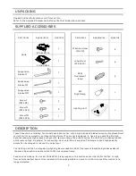
Page 3: ...s direct current motor powered by an integral transformer The motor is designed to have long operating life high dynamic response higher speed ranges with saving energy The grille covering the fan body is a spring loaded quick remove type A damper for preventing air counterflow is provided The blower uses a high capacity sirocco fan developed to reduce the noise level The lighting unit is an energ...

Page 4: ...datpor Fan body Damper Suspension bracket Bracket cover For 16 inches on center joists only use suspension brasket for 19 2 inches on center joists only use suspension bracket If more than 19 2 inches on center joists use suspension brasket III II III 1 2 3 4 5 6 7 8 9 10 11 12 10 1 4 261 13 330 10 8 3 6 2 3 4 70 3 1 2 90 1 25 1 26 4 3 5 116 2 3 4 70 3 1 2 90 1 26 I 4 ...

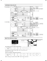
Page 5: ...ite Yellow Lighting unit Black Black White Green Night lamp L L Switch box Black Black Lamp Electronic ballast SWITCH INDICATION Low speed air volume preset switch High low delay time preset switch Switch indications on blower unit Low speed air volume preset switch positions Air Volume CFM 0 30 40 50 60 70 Factory setting 50 CFM Position Use for factory test only Position Fan stop High Low delay ...

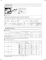
Page 6: ...ions Model No Air direction Voltage V Frequency Hz Duct diameter inches Noise sones Fan body Power consumption W Speed rpm Lighting unit Fluorescent lamp Night lamp Air deliver at 0 1 WG CFM Weight Ib FV 08VKSL2 Exhaust Exhaust 120 60 4 120 60 4 FV 08VKML2 9 6 7 8 6 8 5 9 5 0 1 4 9 6 7 8 6 8 5 9 5 0 18X2 18X2 18X2 18X2 18X2 18X2 18X2 18X2 18X2 18X2 18X2 18X2 4 4 4 4 4 4 4 4 4 4 4 4 723 675 661 625...

Page 7: ...r 2 Installation work and electrical wiring must be done by qualified person s in accordance with all applicable codes and standards including fire rated construction 3 Sufficient air is needed for proper combustion and exhaustiong of gases through the flue chimeny of fuel burning equipment to prevent back drafting Follow the heating equipment manufacturer s guideline and safety standards such as ...

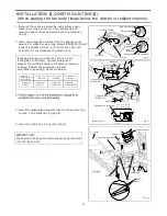
Page 8: ...from damper and adaptor before installation As shown below If spacing A on center joists is 24 inches connect suspension bracket and C4 mark to C4 mark as shown below II III 1 Insert the suspension bracket into the fan body and adaptor Select the suspension bracket as shown below Fan body Fan body Fan body Fan body Suspension bracket I Suspension bracket III Suspension bracket III Suspension brack...

Page 9: ... wiring diagram of page 5 Follow all the local electrical safety codes as well as the National Electrical Code NEC Using UL approved wire nuts connect house power wires to ventilating fan wires black to black white to white green to green For model FV 08VKSL2 connect the two red wires to the switch for the speed control Replace the junction box cover Fig 4 Mount junction box cover carefully so tha...

Page 10: ...he grille and insert other mounting spring into the slot as shown and mount grille to fan body FV 08VKML2 Fig 6 2 Fig 6 3 12 Insert mounting springs into the slots as shown and mount grille to fan body FV 08VKSL2 Fig 7 Mount grille carefully so that lead wire of sensor unit is not pinched CAUTION INSTALLATION JOIST MOUNTING CONTINUED Ceiling Lighting unit Machine screw M4X8 Machine screw M4X8 Scre...

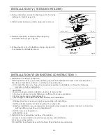
Page 11: ...ews ST4 2X20 Fig 9 Keep the distance B 1 inch 12 7mm or 5 8 inch 15 9mm for the thickness of ceiling board 2 Spacing A between Joists inches mm Suspension bracket Suspension bracket I Suspension bracket III Suspension bracket II III If spacing A between joists is 21 1 4 to 23 1 inches 540 to 597mm connect suspension bracket and C4 mark to C4 mark according to page 8 Select the suspension bracket a...

Page 12: ...y by using screw ST4 2X12 in vertical direction Fig 12 II 8 Follow steps 7 to 12 of Installation page 10 to complete the installation work I C1 C2 C3 C4 Suspension bracket The suspension bracket can comply with different kind of joists III III I 1 Before installation secure the lighting unit to fan body refering to Fig 5 of page 10 2 Connect the suspension bracket to fan body Fig 13 Select the hol...

Page 13: ...g 15 1 Fig 15 2 Fig 16 Fig 17 Fig 18 Joist 2 Long screws ST4 2X20 4 Long screws ST4 2X20 2 Screw ST4 2X12 II Joists Adaptor Junction box Fan body 5 8 15 9 3 Insert the fan body between joists Make sure the fan body is level and square perpendicular with the joists Fig 16 If installing with fan body flange below drywall keep the distance B 1 inch 12 7mm or 5 8 inch 15 9mm for the thickness of ceili...

Page 14: ... Fig 20 4 Follow steps 4 to 12 of installation page 9 page 10 to complete the installation work I Joist Joist Adaptor Adaptor Circular duct 6 Long screws ST4 2X20 Fig 20 Header Fan body Inches mm 1 To install the fan body follow the procedures described in Installation Take the following precautions before installation II 2 Inspect duct work and wiring before proceeding with installation 3 Plan su...

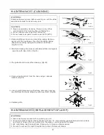
Page 15: ...her such chemicals for cleaning the ventilating fan 2 Do not allow water to get into the motor 3 Do not soak resin parts in water over 140 F 60 C WARNING 1 Disconnect power source before working on unit 2 The lamp s glass is fragile Please handle with care To remove lamp grasp at base and move back and force to loosen Do not pull hard on the lamp or you may break the glass 3 4W night lamp has thre...

Page 16: ...light combination units do not create excessive heat that is a common problem with recessed light fixtures or some competitors fan light combinations Our efficient cool running motors and our fluorescent lamps do not create enough ambient heat to be subjected to these limitations 3 Change the fluorescent lamps Panasonic FDS 18E27 4 18W or FDS18E35 4 18W or FDS18E42 4 18W or the 4W night lamp conne...

Reviews: