INSTALLATION (JOIST MOUNTING- ) CONTINUED
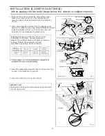
2. Install the suspension bracket and the flange of
fan body to joists by using long screws (ST4.2X20)
(If spacing A between joists is 12 inches, install the
flange of fan body according to Fig.2-1, others
according to Fig.2-2 to install the product)
3. Install the suspension bracket to joists by using
long screws (ST4.2X20) and secure it to the fan
body by using screw (ST4.2X12) (Fig.3)
II
4. Remove junction box cover and secure conduit
or stress relief to junction box knock-out hole.
(Fig.4)
6. Install a circular duct and secure it with
duct tape or clamps.
5. Refer to wiring diagram of page 5.
Follow all the local electrical safety codes as
well as the National Electrical Code (NEC).
Using UL approved wire nuts, connect house
power wires to ventilating fan wires:
black to black; white to white; green to green;
For model FV-08VKSL2 connect the two
red wires to the switch for the speed control.
Replace the junction box cover. (Fig.4)
Mount junction box cover carefully so that
lead wires are not pinched.
CAUTION:
Joist
Joist
Joist
Duct tape
or clamps
Circular duct
Conduit
(FV-08VKML2)
(FV-08VKSL2)
Junction box cover
Fig.2-1
Fig.2-2
Fig.3
Fig.4
Fan body
Fan body
2 Long screws
(ST4.2X20)
2 Long screws
(ST4.2X20)
Screws
(ST4.2X12)
II
4 Long screws (ST4.2X20)
Joist
9
Conduit
Red wires
Green wires
Lead wires
Wire nut
Junction box
Green wires
Lead wires
Wire nut
Junction box
Conduit
PDF created with pdfFactory Pro trial version
www.pdffactory.com

