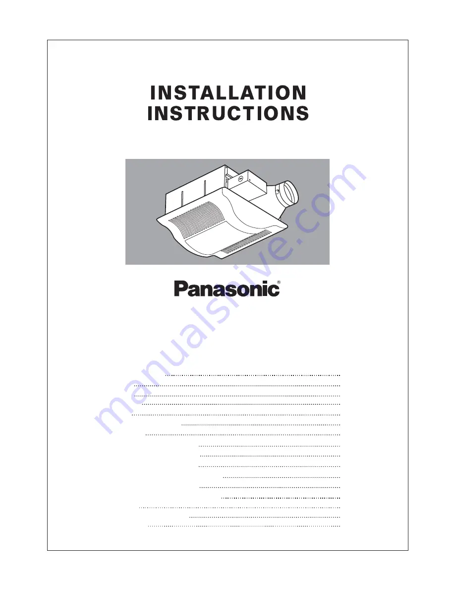
Ventilating Fan
FV-08VSL1
R
EAD AND SAVE THESE INSTRUCTIONS.
R
Please read these instructions carefully before attempting to install,
operate or service the Panasonic Ventilating Fan. Failure to comply
with instructions could result in personal injury and/or property
damage. Please retain this booklet for future reference.
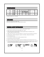
Specifications
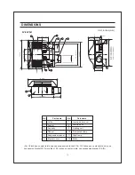
Dimensions
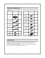
Description
12
11-12
13-14
14
6-8
4
4-5
4
3
2
2
Table of Contents
Supplied Accessories
Unpacking
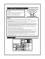
General Safety Information
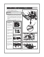
I
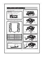
Installation
( Wooden Header )
10
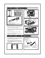
III
( -Joist Mounting )
I
10-11
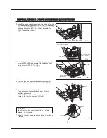
Installation
( Between Joist Mounting )
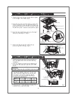
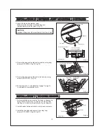
Installation
( In Existing Construction )
VI
Installation
( Joist Mounting- )
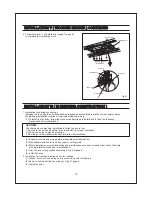
I
Installation
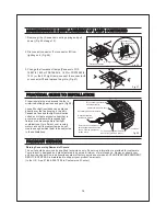
Maintenance
Practical Guide to Installation
14
Product Service
8-9
II
( Joist Mounting-
)
II
Installation
IV
V
Wiring Diagram
5


