background image

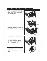
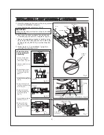
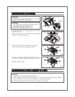
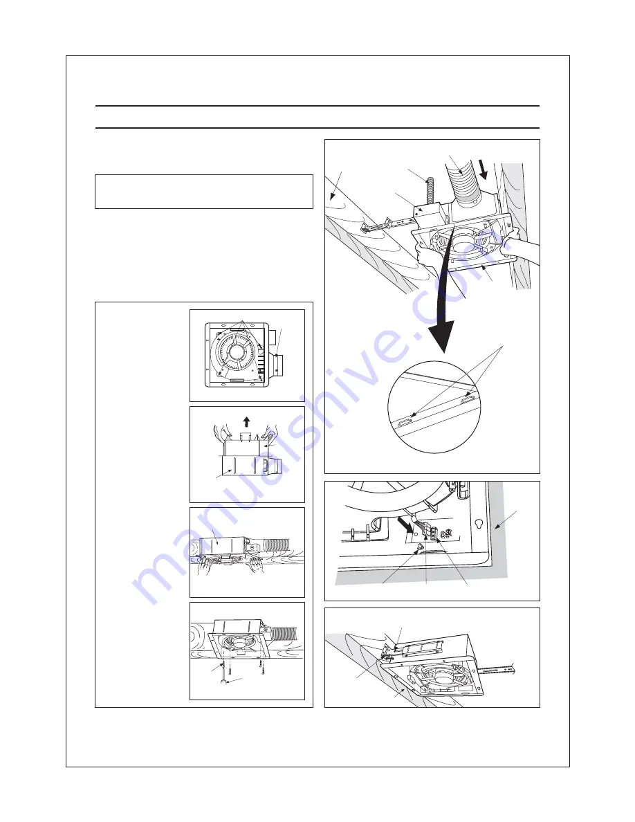
Make sure that adaptor claws are properly inserted
into body slots.

IMPORTANT:

5. Insert the fan body into joists. (Fig.9)

6. Secure the fan body to adaptor by using thumb

screw and plug connector to receptacle. (Fig.10)

INSTALLATION

JOIST MOUNTING-

CONTINUED

II

II

(

)

INSTALLATION

JOIST MOUNTING-

CONTINUED

II

II

(

)

When mounting
body and blower
separately

1. Loosen 4 screws (but

do not remove them
from blower). (Fig.12-1)

2. Remove blower section.

(Fig.12-2)

4. Insert fan body (without

blower section) into joists.
(Fig.9)

5. Secure the adaptor to

fan body by using thumb
screw. (Fig.10)

7. Insert the blower into the

fan body. (Fig.12-3)

8. Secure the blower.

(Fig.12-4) and plug
connector to receptacle.
(Fig.10)

3. Remove adaptor from

fan body and secure it
to joists as in Fig.8 of
page 8.

9

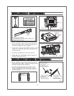
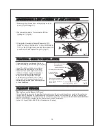
7. Secure

to joists by using

long screws (ST4.2X20) and secure it to fan body
by using screw

(ST4.2X12) in vertical direction.

(Fig.11)

the suspension bracket

II

8. Follow step 8 to 11 of installation (page 8) to

complete the installation work.

I

Fig. 9

4. Insert

to fan body (refering

to step 2 of installation , page 6).

the suspension bracket in

I

Fig. 11

2 Long screws
(ST4.2X20)

Screw

(ST4.2X12)

II

6. Secure the fan body

to joists by using long
screw (ST4.2X20).
(Fig.11)

Conduit

Junction box cover

Circular duct

Joist

Fan body

Adaptor
claws

Fig.12-1

Adaptor

4 Screws

Fig.12-4

4 Screws

Screw driver

Fig.12-3

Fan body

Fig.12-2

Fan body

Blower

Fig. 10

Thumb

screw

Plug connector

I

Receptacle

I

Ceiling

Joist

Summary of Contents for Whisper Value-Lite FV-08VSL1

Page 1: ...this booklet for future reference Specifications Dimensions Description 12 11 12 13 14 14 6 8 4 4 5 4 3 2 2 Table of Contents Supplied Accessories Unpacking General Safety Information I Installation Wooden Header 10 III Joist Mounting I 10 11 Installation Between Joist Mounting Installation In Existing Construction VI Installation Joist Mounting I Installation Maintenance Practical Guide to Instal...

Page 2: ...nded service life with reduced energy consumption It also incorporates a thermal cutoff for safety The grille covering the main body is a spring loaded quick release type A damper for preventing counterflow is provided The lighting unit is an energy saving lighting device which uses two 18W fluorescent lamps and produces almost the same illumination as a standard 100W incandescent lamp Quantity Ap...

Page 3: ...1 Junction box cover Junction box Lighting unit Fluorescent lamp Night lamp Part name No Part name No 1 2 3 4 5 6 7 8 9 10 11 Damper Fan body Adaptor Grille Suspension bracket Bracket cover 7 9 11 10 1 0 1 4 2 6 1 1 2 3 0 0 3 76 13 330 10 1 4 261 3 3 4 94 6 13 330 2 7 8 73 1 2 13 3 6 8 95 3 1 8 78 3 1 8 78 1 1 2 38 1 25 2 3 8 60 8 13 1 4 15 1 2 336 394 16 1 2 18 3 4 419 480 21 1 4 23 1 2 540 597 1...

Page 4: ...ght fixture or junction box 5 Protect the power cord from sharp edges oil grease hot surfaces chemicals or other objects 6 Do not kink the power cord 7 Do not install the unit where ducts are configured as shown in Fig A 8 Provide suction parts with proper ventilation 9 This unit is UL listed for use over a bathtub or shower when installed in a GFCI protected branch circuit Noise sones Duct diamet...

Page 5: ...ng Engineers ASHRAE and the local code authorities E Ducted fans must always be vented to the outdoors F These models are UL listed for tub and shower enclosures G Solid state controls may cause harmonic distortion which can cause motor humming noise To reduce the risk of fire or electric shock do not use this unit with any solid state control device J Not to be installed in a ceiling thermally in...

Page 6: ...3 Refer to Fig 2 4 If spacing A on center joists is 24 inches connect suspension bracket and C4 mark to C4 mark as shown below II III Joists A 1 Before installation secure the fan body to adaptor by using thumb screw Fig 1 IMPORTANT Remove the tape from damper and adaptor before installation As shown below Suspension bracket I Fig 2 1 Fan body Suspension bracket I Suspension bracket III Fig 2 2 Fa...

Page 7: ...t hole Fig 5 6 Refer to wiring diagram page 5 Using wire nuts connect house power wires to ventilating fan wires black to black white to white green to green Replace the junction box cover Fig 5 CAUTION Mount junction box cover carefully so that lead wires are not pinched 7 Install a circular duct and secure it with duct tape or clamps 3 Install the suspension bracket and the flange of fan body to...

Page 8: ...TION JOIST MOUNTING II II 3 Follow step 5 to 7 of the installation page 7 to complete the duct work and wiring I If spacing A between joists is 21 1 4 to 23 1 2 inches connect suspension bracket and C4 mark to C4 mark according to page 6 Select the suspension bracket according to spacing A as shown below II III suspension bracket suspension bracket I suspension bracket III suspension bracket II II...

Page 9: ... blower Fig 12 4 and plug connector to receptacle Fig 10 3 Remove adaptor from fan body and secure it to joists as in Fig 8 of page 8 9 7 Secure to joists by using long screws ST4 2X20 and secure it to fan body by using screw ST4 2X12 in vertical direction Fig 11 the suspension bracket II 8 Follow step 8 to 11 of installation page 8 to complete the installation work I Fig 9 4 Insert to fan body re...

Page 10: ...an body refering to Fig 6 of page 8 fan body adaptor 2 Insert the suspension bracket into bracket cover of adaptor side and the back of the fan body Fig 16 select the suspension bracket according to spacing A as shown below Fig 14 Screw ST4 2X12 II Suspension bracket III Fig 16 Suspension bracket Suspension bracket I III 16 inches and 19 2 inches horizontal joist 19 2 inches vertical joist Suspens...

Page 11: ...4 2X20 Fig 18 Fig 19 5 Secure the suspension bracket to fan body by using screw ST4 2X12 Fig 19 II 6 Follow step 5 to 11 of installation page 7 page 8 to complete the installation work I INSTALLATION WOODEN HEADE V R INSTALLATION WOODEN HEADE V R INSTALLATION JOIST MOUNTING IV BETWEEN CONTINUED INSTALLATION JOIST MOUNTING IV BETWEEN CONTINUED Fig 18 Fig 17 inches mm Junction box Fan body Joists Ad...

Page 12: ... Wiring can be run to planning location 3 No wiring or other obstructions shall interfere with installation 2 Inspect duct work and wiring before proceeding with installation 3 Plan suitable location for fan body next to ceiling joist 5 First remove ceiling section according to Fig 6 of page 8 6 Install fan body 1 Inspect duct work and wiring before proceeding with installation 2 Remove ceiling se...

Page 13: ...w cloth Fig 23 Fig 23 3 Remove dust and dirt from fan body using a vacuum cleaner Remove lamps if necessary Fig 24 4 Using a cloth dampened with kitchen detergent remove any dirt from fan body Wipe dry with new cloth Fig 25 5 Replace lamps and grille MAINTENANCE II REPLACEMENT OF LAMP MAINTENANCE II REPLACEMENT OF LAMP 1 Disconnect power source before working on unit 2 The lamp s glass is fragile ...

Page 14: ... 1 866 292 7292 to Customer call Center P ODUCT SE VICE R R P ODUCT SE VICE R R Loose fill or batt insulation can be placed directly over the fan housing in the attic Panasonic fans and fan light combination units do not create excessive heat that is a common problem with recessed light fixtures or some competitors fan light combinations Our efficient cool running motors and our fluorescent lamps ...

Page 15: ...SUMER ELECTRONICS COMPANY Division of Panasonic Corporation of North America PANASONIC CANADA INC 5770 Ambler Driver Mississauga ON L4W 2T3 www panasonic com One Panasonic Way Secaucus NJ 07094 X0606 6048 08VSL1420F ...

Reviews: