Service Manual
PEG1311049CE
Version:1401
CONTENTS
PAGE
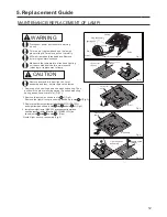
Ventilating Fan
(North America Market)
WhisperLite
TM
WARNING
This service information is designed for experienced repair technicians only and is not designed for use by
the general public. It does not contain warnings or cautions to advise non-technical individuals of potential
dangers in attempting to service a product. Products powered by electricity should be serviced or repaired
only by experienced professional technicians. Any attempt to service or repair the product or products dealt
with in this service information by anyone else could result in serious injury or death.
IMPORTANT SAFETY NOTICE
There are special components used in this equipment which are important for safety. These parts are
marked by in the Schematic Diagrams, Exploded Views and Replacement Parts List. It is essential
that these critical parts should be replaced with manufacturer's specified parts to prevent shock, fire
or other hazards. Do not modify the original design without permission of manufacture.
We suggest to handle such parts after the static electricity prevention.
It is forbidden to touch the PCB parts by bare hands during the repairing process.
FV-08VQL5
FV-11VQL5
FV-15VQL5
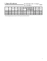
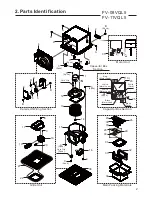
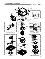
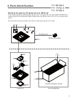
2.Parts Identification
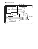
3.Wiring Diagram
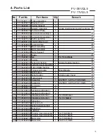
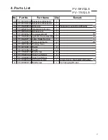
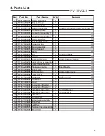
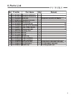
4.Parts List
2~4
6~9
5
1.Specifications
1
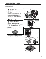
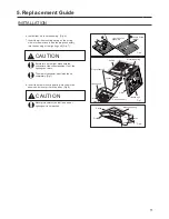
5.Replacement Guide
10~12


