10
5.Replacement Guide
INSTALLATION
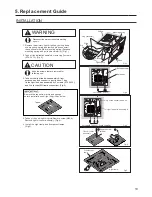
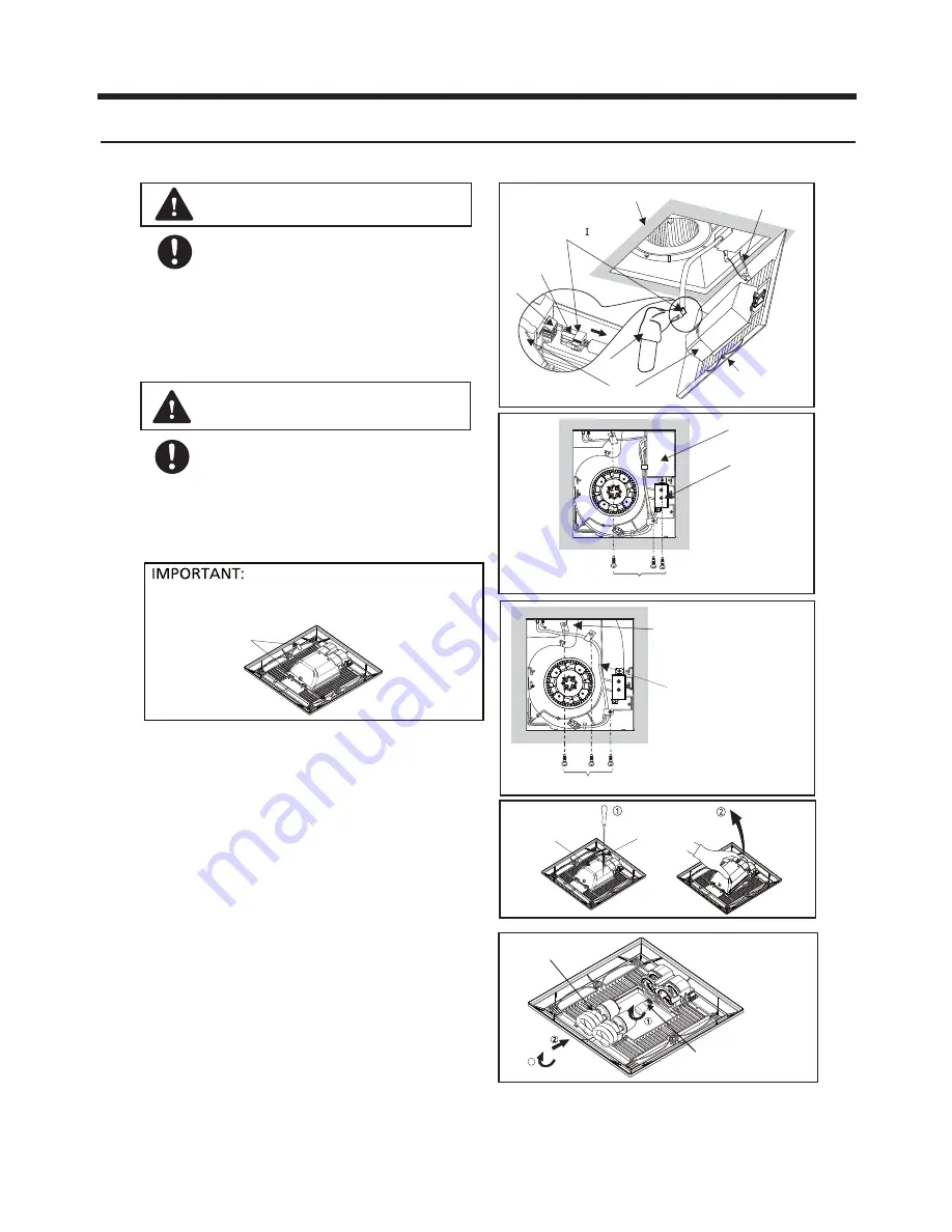
2. Take off the ballast assembly by removing 3 screws
(ST4.2X12). (Fig.2)
Ceiling
Grille
Gloves
Rib
Claw
Ballast Assembly
Switch box
Lighting unit
Plug connector
Mounting spring
Fig.3
Fig.4
Only fix the sensor lead wire.
Fig.1
Light lead wire assembly A
3 screws(ST4.2X12)
Fig.2
3 screws(ST4.2X12),3 cord clips(5N)
Remove the tapes from grille and springs
before installation new light kit grille as below
Tapes
Light kit cover
assembly
Remove screw
(M4X8)
3. Take out the light lead wire assembly A from
accessories, and connect to junction box. Then
fix the light lead wire assembly by 3 screws (ST4.2X12),
and 3 cord clips(5N,from accessories).(Fig.3)
1. Remove the primary light kit grille by pulling down
one mounting spring and remove plug connector ,
then pull down the other mounting spring (Squeeze
mounting spring and pull down carefully) (Fig.1)
Ⅰ
.
Keep the screws that are removed for
following use.
CAUTION
Disconnect power source before working
on unit.
WARNING
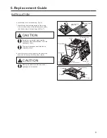
4.Take out the new light kit grille.Remove screw(M4X8).
Remove light kit cover assembly. (Fig.4)
3
Fig.5
Fluorescent
lamp
Night lamp
5. Install the night lamp and fluorescent lamps.
(Fig.5)

