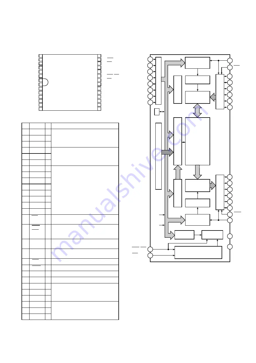
21
Vss 22
SOD2 27
SOD1 26
SOD3 28
SOD5 2
SID4 4
SID6 6
8 IR6/A6
10 IR4/A4
12 IR2/A2
14 A8/A0
16 RAS/IRE
18 SOC
20 SOE
SID1 23
SID3 25
SID2 24
SOD4 1
SOD6 3
SID5 5
IR7/A7 7
9 IR5/A5
11 IR3/A3
13 IR1/A1
15 IRS/CAS
17 SIC
19 SIE
21 Vcc
Pin
Name
I/O Description
1 SOD4
O
2 SOD5
O Serial Data output terminals. (6-Bit)
3 SOD6
O
4 SID4
I
5 SID5
I Serial Data input terminals (6-Bit).
6 SID6
I
7 IR7/A7
I
8 IR6/A6
I
9
IR5/A5
I
10
IR4/A4
I
11
IR3/A3
I
12
IR2/A2
I
13
IR1/A1
I
14 A8/A0
I
22 Vss –
Ground terminal.
23 SID1
I
24 SID2
I
Serial Data input terminals. (6-Bit)
25 SID3
I
15 IRS/
I
Instruction Strobe signal and Column
CAS
Address Strobe signal input terminal.
16
RAS/
I
Row Address Strobe signal and
IRE
Instruction enable signal input
terminal.
17
SIC
I Serial Data In Clock Pulse input
terminal.
18
SOC
I Serial Data Out Clock Pulse input
terminal.
19 SIE
I Serial Data input enable
terminal.
20 SOE
I Serial Data output enable terminal.
21 Vcc –
Power supply terminal.
Instruction Code, Column Address
and Row Address input terminals.
(8-Bit)
(TOP VIEW)
Timing Generator
Instruction
Register
Instruction
Decoder
Output Row
Address
Counter
Output Row
Decoder
Output Serial
Memory
(256 x 6)
Output Column
Address Counter
Serial Output Buffer
Column Decoder
1/320
Memory Array
(320 x 256 x 6)
Input Serial
Memory
(256 x 6)
Input Row
Decoder
Input Row
Address
Counter
Input Column
Address Counter
Serial Input Buffer
Instruction Address Buffer
A8
Memory Reflesh Column Address Counter
0
Column
Address
0 Row
Address
20
19
18
17
16
15
14
24
26
2
3
4
11
12
13
5
6
7
8
9
10
27
25
23
Vss
Vcc
RAS/IRE
IRS/CAS
SOD1
SOD2
SOD3
SOD4
SOD5
SOD6
SOE
SOC
SIC
SIE
SID1
SID2
SID3
SID4
SID5
SID6
A8/A0
IR1/A1
IR2/A2
IR3/A3
IR4/A4
IR5/A5
IR6/A6
IR7/A7
28
1
26 SOD1
O
27 SOD2
O Serial Data output terminals. (6-Bit)
28 SOD3
O
21
22
1.8.
IC832 to IC843 on the Main Board are using the Field Memory IC YWM5M4C500AV.
Description of this IC is as follows:


