22
b
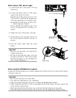
Connect the RJ11 modular cable to the RS-485 port.
RS-485
RB
RA
TB
TA
OUT
GND
IN
GND
6
5 4
3 2
1
3
2
RA
RB
Receive
5
4
TA
TB
Transmit
WJ-GXE500 (WJ-GXE500E)
Signal
To the connected device
Important:
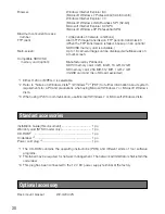
• The RS-485 connector of this unit is intended for the 4-wire communication.
When connecting cameras for the 2-wire communication in the daisy chain, do as the following
illustration describes.
4 3 2 1
RS-485
SIGNAL
GND
12V IN
2
1
4
3
VIDEO IN
MIC/LINE
IN
SET SW
AUDIO
OUT
EXT I/O
Camera 4
Camera 3
Camera 2
Camera 1
RS-485 (2-wire)
2-wire
4-wire
A
TA TB RA RB
B
• When connecting cameras and units in the daisy chain, set the RS-485 terminal switch of the
units at the connection ends to ON and other units to OFF. (
☞
page 15)
n
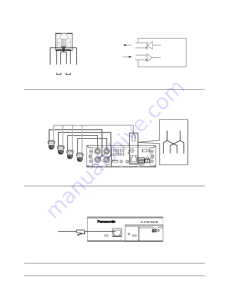
Connect a LAN cable (category 5 or better) to the network connector on the front of the unit.
ACT
LINK
Network Video Encoder
WJ-GXE500
10BASE-T/100BASE-TX
OPERATE
SD CARD
ERROR
LAN cable (category 5 or
better, straight (NTSC
model) / category 5 or
better, straight, STP
(PAL model))
m
Connect the power cord.
Important:
• The power supply of 12 V DC shall be insulated against 120 V AC or 220 V - 240 V AC.

