background image


71 


Clicking “

” to save event log information currently displayed in the list as a text file. 


The date and time are displayed. 


Click the camera button (1 to 8 or 4) to select the camera to be viewed. 


Click the screen format to select the desired display mode.  When changing the screen format, the 
selected camera on the current screen will be located in the first cell of the new layout. 


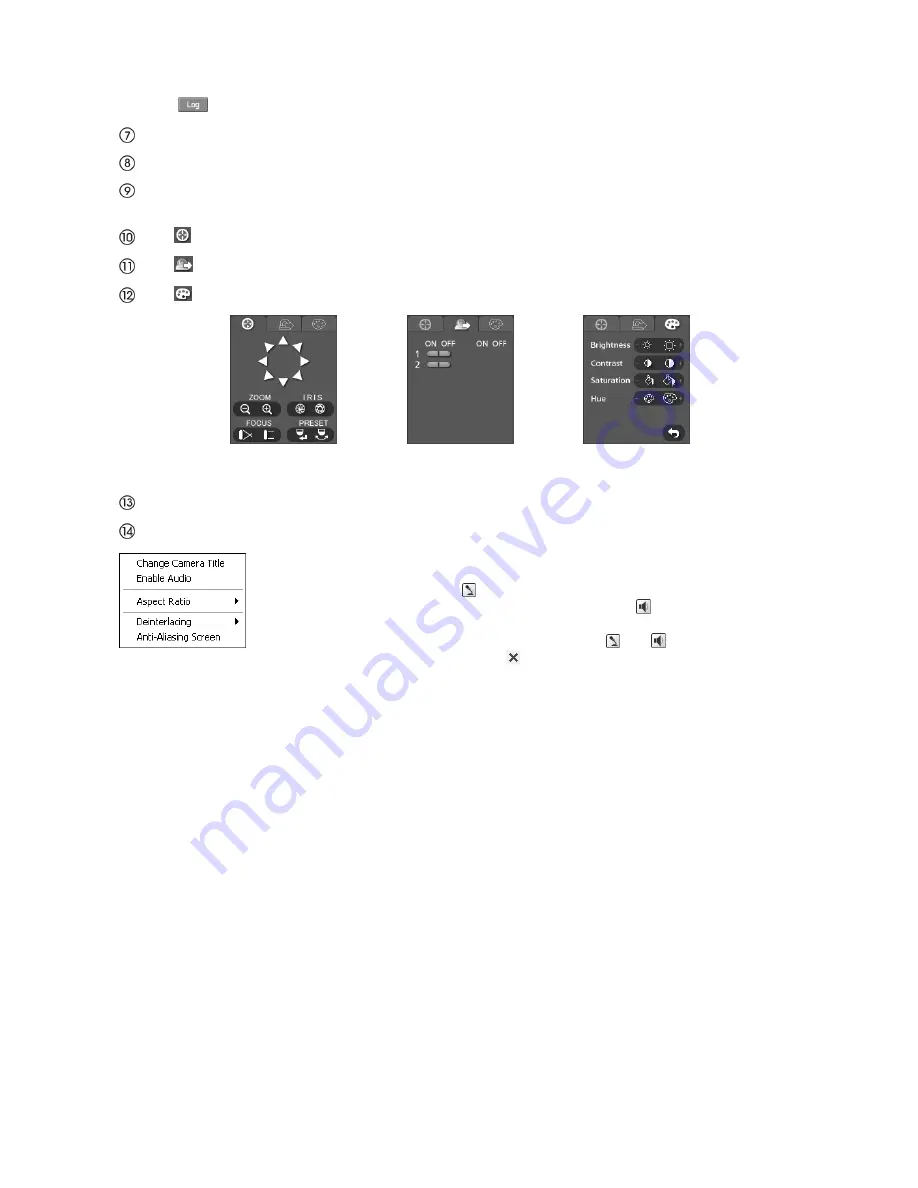
Click “ ” to control pan, tilt, zoom, iris, focus, and preset of the camera from a web browser. 


Click “

” to control alarm out devices at the web browser. 


Click “

” to adjust the brightness, contrast, saturation and hue of monitoring image. 


Note:  During controlling camera from the recorder, you cannot control any camera. 


The event status window at the bottom displays a list of events that are detected from the recorder. 


Selecting a camera on the screen and clicking the right mouse button displays the context menu. 


Change Camera Title

 : Changes the camera name.  

Enable Audio

 : Enables audio communication with the web browser. When the audio 

control panel displays, click the   button to send audio to the connected web browser 
and click the button again to stop sending audio.  Click the    button to monitor live 
audio from the connected web browser through the attached speaker and click the 
button again stop monitoring live audio.  Clicking both   and   buttons allows 
two-way communication.  Clicking the   button disables audio communication. 


Aspect Ratio

 : Changes the image aspect ratio. 

Deinterlacing

 : Using a deinterlace filter for interlaced video enhances image display quality by eliminating 

horizontal scan lines and noise in areas with motion.  It is effective only when the Network-Resolution is "Very 
High"(D1). 

Anti-Aliasing Screen

 : Enhances image display quality by eliminating stair stepping (aliasing) effects in the 

enlarged image. 
 

Note:  A Camera Title change in the Watch mode does not affect the camera name on the 

recorder.  Leaving the Camera Title blank causes the camera name set up in the Camera – 
Settings screen to display. 


Summary of Contents for WJ-HL204/G

Page 1: ...del No WJ HL204 G WJ HL208 G Before attempting to connect or operate this product please read these instructions carefully and save this manual for future use The model number is abbreviated in some descriptions in this manual WJ HL208 G WJ HL204 G ...

Page 2: ...rjoja jotka noudattavat direktiivien 2006 95 EC ja 2004 108 EC säädöksiä Vi erklærer oss alene ansvarlige for at produktet som denne erklæringen gjelder for er i overensstemmelse med følgende normer eller andre normgivende dokumenter som følger bestemmelsene i direktivene 2006 95 EC og 2004 108 EC CAUTION TO REDUCE THE RISK OF ELECTRIC SHOCK DO NOT REMOVE COVER OR BACK NO USER SERVICEABLE PARTS IN...

Page 3: ...F THE CUT OFF PLUG IS INSERTED INTO ANY 13 AMP SOCKET If a new plug is to be fitted please observe the wiring code as shown below If in any doubt please consult a qualified electrician WARNING This apparatus must be earthed IMPORTANT The wires in this mains lead are coloured in accordance with the following code Green and yellow Earth Blue Neutral Brown Live As the colours of the wire in the mains...

Page 4: ...ECTION OR SLIP UP IN DETECTION BY MOTION DETECTION AND MOTION SEARCH FUNCTIONS OF THE PRODUCT Trademarks and registered trademarks Adobe Adobe logo and Reader are either registered trademarks or trademarks of Adobe Systems Incorporated in the United States and or other countries Microsoft Windows Windows Vista Internet Explorer and DirectX are either registered trademarks or trademarks of Microsof...

Page 5: ...nto your outlet consult an electrician forreplacement of the obsolete outlet 10 Protect the power cord from being walked on or pinched particularlyat plugs convenience receptacles and the point where they exit from the apparatus 11 Onlyuse attachments accessories specified bythe manufacturer 12 Use onlywith the cart stand tripod bracket or tablespecified bythe manufacturer or sold with the apparat...

Page 6: ...nce the power is turned off Ask your dealer when replacement of the battery is required Hard disk drive HDD Hard disk drives are vulnerable to vibration Handle them with care It is possible to damage them if they are moved while their motors are still running Do not move them just after turning the power off for around 30 seconds The lifetime of hard disk drives is limited by use Write errors may ...

Page 7: ...ion This product is designed for indoor use Avoid the following locations for installation Locations exposed to direct sunlight Places subject to having strong vibration or impact Near magnetic field sources such as a television or speakers Place where condensation forms easily where temperature changes greatly humid places Steamy and oily places such as kitchens Places which are not level Places ...

Page 8: ...power outlet and connect the power cord via the power plug Connect the power cord to the breaker with contact gap of 3 0 mm or more of a distribution board The breaker shall be able to shut down all the poles of the main power supply except the ground protective conductor For BNC cable connection Use only the recommended plug below when connecting the BNC plug to the connectors on the rear panel o...

Page 9: ...Buttons 1 to 8 or 4 18 HDD Indicator HDD 19 Alarm Indicator ALARM 19 Link Indicator LINK 19 Copy Indicator COPY 19 Operate Indicator OPERATE 19 Mouse Copy Port MOUSE COPY 19 Arrow Buttons 19 Play Pause Button 19 Menu PTZ Button MENU or PTZ 19 Playback Edit Group Button PLAYBACK or EDIT GROUP 20 Next Group Sequence Button NEXT GROUP or SEQ 20 Multiscreen Spot Button MULTISCREEN or SPOT 20 EL Zoom R...

Page 10: ...cording Video 56 Panic Recording 56 Recording Audio 56 Playing Recorded Video 56 Searching Video 58 Search Menu 58 Event Log Search 60 Record Table Search 61 Calendar Search 62 Motion Search 62 Clip Copy 63 Appendix 66 Display Setup Menu of Camera 66 System requirements for a PC 66 Clip Player 67 Web Browser 69 Watch Mode 70 Search Mode 72 Time Overlap 74 Pin Outs 75 Alarm Input Output 75 RS485 75...

Page 11: ...Figure 26 New User User Information screen 28 Figure 27 Shutdown screen 29 Figure 28 Network menu 29 Figure 29 Network Network screen 29 Figure 30 Network LAN Manual screen 30 Figure 31 Port Number Setup screen 30 Figure 32 Network LAN DHCP screen 31 Figure 33 Network Web Browser screen 31 Figure 34 Mail screen 31 Figure 35 Authentication screen 32 Figure 36 Devices menu 32 Figure 37 Camera Settin...

Page 12: ...47 Figure 77 System Event Health Check screen 48 Figure 78 Check Recording screen 48 Figure 79 System Event Storage screen 48 Figure 80 System Event Actions screen 49 Figure 81 Event Status Event Status screen 49 Figure 82 Live Monitoring menu 50 Figure 83 Sequence pattern 51 Figure 84 Camera menu 51 Figure 85 PTZ Select Camera menu 53 Figure 86 PTZ Preset menu 53 Figure 87 Advanced PTZ menu 53 Fi...

Page 13: ...rowser and during playback Self diagnostics with automatic notification including HDD S M A R T protocol Equipped with 3 HDD slots Technical Overview In addition to replacing both a time lapse VCR and a multiplexer in a security installation your recorder has many features that make it much more powerful and easier to use than even the most advanced VCR The recorder converts analog PAL video to di...

Page 14: ...pgrade the system or copy video clips to external flash drives Note This manual covers the 8 and 4 channel digital disk recorders The recorders are almost the same specification except for the number of cameras and alarms that can be connected and the number of cameras that can be displayed In the 4 channel model a part of function is not equipped For simplicity the illustrations and descriptions ...

Page 15: ...cable 2 HDD Fixing Screw 12 including 4 as spares CD ROM 1 The CD ROM contains the regulations documents and important safety instructions PDFs written in the following language French German Spanish Italian and Russian Adobe Reader is required to read the PDF files on the provided CD ROM When Adobe Reader is not installed on the PC download the latest Adobe Reader from the Adobe web site and inst...

Page 16: ...er can be used with PAL equipment Video Input Connector VIDEO IN 1 to 8 or 4 Connect the coaxial cables from the video sources to the Video Input BNC connectors The 4 channel model has 4 Video Input BNC connectors VIDEO IN 1 to 4 Video Output Connector VIDEO OUT 1 to 8 or 4 If you would like to connect your video source to another device you can use the Video Output BNC connectors The 4 channel mo...

Page 17: ...M and NO Normally Open terminals NC NO is a relay output which sinks 1 A 30 Vpeak maximum See Chapter 3 Configuration for configuring alarm output ARI Alarm Reset In An external signal to the Alarm Reset In can be used to reset both the Alarm Out signal and the recorder s internal buzzer Mechanical or electrical switches can be wired to the ARI Alarm Reset In and GND Ground terminals The threshold...

Page 18: ...have saved Excluded camera titles you can change in the Web Browser To reset the unit you will need a straightened paperclip 1 Turn the recorder off 2 Turn it on again with insert the straightened paperclip into the unlabeled hole in the left of the MON 3 VGA connector or the right of the Serial Port 4 channel model Note Continue inserting until the internal buzzer starts to sound approximately 30...

Page 19: ... Spot Button EL Zoom Return Button Copy Preset View Button Alarm Preset Set Button Panic Button The front panel looks and operates much like a VCR combined with a multiplexer Many of the buttons have multiple functions The following describes each button and control Take a few minutes to review the descriptions You will use these to initially set up your recorder and for daily operations Note You ...

Page 20: ...e used to navigate through menus and GUI You can also use them to change numbers by highlighting a number in the menu and using the Up and Down arrow buttons to increase or decrease the number s value These buttons are also used to control Pan and Tilt when in the PTZ mode When in the PIP display format pressing the Up and Down arrow buttons moves the position of the small screen counter clockwise...

Page 21: ...ode Next Group Sequence Button NEXT GROUP or SEQ When in the live mode pressing the NEXT GROUP button changes the screen from the current camera group to the next camera group and the screen displays the page number The 4 channel model s multi screen is excluded Pressing and holding the SEQ button for three seconds or longer displays live channels sequentially Multiscreen Spot Button MULTISCREEN o...

Page 22: ... mouse pointer to the top of the screen and then select Login in the Live Monitoring menu to enter the setup screens The Login screen appears Select a User and enter the password by pressing the appropriate combination of Camera number buttons and then the button Enter the password default 1234 when logging in the ADMIN user default for the first time Figure 6 Login screen Note To assure the secur...

Page 23: ...tles When making these entries a Virtual Keyboard will appear Use the arrow keys to highlight the character you want in the name or title and press the button That character appears in the title bar and the cursor moves to the next position Pressing toggles between the upper and lower case keyboards backspaces and deletes entered characters You can use up to 31 characters including spaces in your ...

Page 24: ...e upgrade package file to the recorder Highlight Upgrade and press the button The Upgrade screen appears Figure 12 Upgrade screen The screen displays the upgrade package file names that are available The rui indicates that the file is for software upgrades Select the desired file and press the button Highlighting the Install button and pressing the button will install the selected software package...

Page 25: ... bottom left of the screen Figure 15 System Log screen To export the System Log connect the USB flash drive to the recorder Highlight Export and press the button Highlight the box beside File name and press the button Figure 16 System Log Export screen A virtual keyboard allows you to enter the file name Selecting Export will save the System Log in txt file format on the USB flash drive Highlighti...

Page 26: ...he three available time formats and press the button to save your selected format Note The clock will not start running until you have highlighted Save and pressed the button Highlight the box beside Time Zone and press the button Select your time zone from the list and press the button Highlight Use Daylight Saving Time and press the button Pressing the button toggles between On and Off Highlight...

Page 27: ...ighlighting Save and pressing the button Selecting Cancel exits the screen without saving the changes Storage Highlight Storage in the System menu and press the button The Storage setup screen appears and displays information about the recorder s storage devices The information in the Type column describes the storage device The capacity of the storage device is displayed in the Capacity column Th...

Page 28: ...ntact your dealer as soon as possible Temperature and S M A R T information will be available only for internal hard disk drives supporting the SMART Self Monitoring Analysis and Reporting Technology monitoring program Selecting Close and pressing the button exits the screen User Highlight User in the System menu and press the button The User setup screen displays the authorized groups and users Y...

Page 29: ...ve video data in an AVI bitmap or JPEG file format Setup The user without Setup authority cannot establish any system settings excluding system shutdown and logout on a local system System Time Change The user can change the system date and time on a local system Data Clear The user can clear all video data or format disks on a local system PTZ Control The user can control the PTZ camera on a loca...

Page 30: ...r from 1 00 ips to 25 00 ips Highlight the second box beside bps ips You can select the unit of measure for the transfer speed between bps and ips Press the button to set the transfer speed Highlight the box beside Quality and press the button You can select the Quality from Very High High Standard and Basic Press the button to set the Quality Figure 29 Network Network screen Highlight the box bes...

Page 31: ...ress 192 168 0 250 Default Gateway 192 168 0 1 Subnet Mask 255 255 255 0 Figure 30 Network LAN Manual screen Note You will need to get the appropriate IP Address Default Gateway and Subnet Mask from your network administrator Highlight the box beside DNS Server Press the Up and Down arrow buttons to set the IP address of the DNS server Highlight the Port Number Setup box and press the button The P...

Page 32: ...ult port number is 12088 Figure 33 Network Web Browser screen You can save your Network changes by highlighting Save and pressing the button Selecting Cancel exits the screen without saving the changes Mail The recorder can be set up to send an e mail when an event occurs Highlight Mail in the Network menu and press the button The Mail screen displays You will be able to change the Mail settings H...

Page 33: ...rd to enter the e mail address You can save your Mail changes by highlighting Save and pressing the button Selecting Cancel exits the screen without saving the changes Devices Setup You can configure the video audio alarm and display Figure 36 Devices menu Camera Highlight Camera in the Devices menu and press the button The Camera setup screen appears You can turn the camera number On or Off and y...

Page 34: ...he PTZ ID number can be set from 1 to 96 Highlight the Setup and press the button The Port Setup screen appears Configure the port s setting based on the PTZ camera manufacturer s instructions Figure 40 Port Setup screen You can save your Camera changes by highlighting Save and pressing the button Selecting Cancel exits the screen without saving the changes Audio Highlight Audio in the Devices men...

Page 35: ...chedule tab causes the Schedule screen to display You can add and edit alarm output schedules on this screen Highlight the and press the button to add a schedule Highlighting the boxes under the Column heading and pressing the button allows you to edit the information in those boxes The Day box allows you to select the days that the alarm schedule will be active The choices are Sun Mon Tue Wed Thu...

Page 36: ...ay on each camera screen Audio The icon displays on each camera screen for which the recorder can play live audio on a local system PTZ The icon displays on each PTZ camera screen You can adjust the transparency of the setup screens by highlighting the slide bar beside Transparency and using the Left and Right arrow buttons Highlighting OSD Margin and pressing the button displays how OSD text will...

Page 37: ...1 second to 1 minute Highlight Event Monitoring On and press the button Pressing the button toggles between On and Off When it is On the recorder will display the camera associated with the event when an event occurs Highlight the Spot Monitor tab to switch to the Spot Monitor screen You can define which cameras display sequentially on the Spot Monitor Highlight the box in the Channels column and ...

Page 38: ...f the recorder stops recording once all available storage space has been used Highlight the Event Record Dwell box and set the length of time you would like to record for the associated event You can set the dwell from 5 seconds to 30 minutes Simple Mode only Refer to Event Actions screen in this chapter for information regarding event recording Figure 51 Record Settings screen Highlighting De Int...

Page 39: ...ks sequentially based on time And these sequentially recorded videos have the advantage that you can search recorded video easily even though a disk is removed from the unit However video recorded in the same time range might be saved on different disks by channel and by the type of recording mode Once the Limit Time Lapse Recording is set to On the recorder will maintain this recording limitation...

Page 40: ...the time range that the scheduled recording will take place The smallest time segment you can use is 15 minutes Highlight the box under the Mode heading and press the button to change the recording mode that will be used Choose from No Record Time Event and Time Event Simple Mode Only When the recorder is in the No Record mode it will not record during the preset day and time range as long as the ...

Page 41: ...tton to delete the recording settings You will be asked to confirm that you want to delete the settings Highlight Default and press the button The Default screen appears Highlighting boxes under ips and pressing the button allows you to set the images per second for Time and Event recording You can select from 1 00 ips to 25 00 ips Figure 55 Default Schedule Advanced Mode screen Highlighting boxes...

Page 42: ...hlighting Save and pressing the button Selecting Cancel exits the screen without saving the changes Note The Pre Event settings might change automatically by the constraint performance when you save your changes Event Setup Your recorder can be set to detect many different events You can also determine how it reacts to these events Figure 57 Event menu Alarm In Highlight Alarm In in the Event menu...

Page 43: ...lso set the recorder s internal buzzer to sound Note For the Alarm Out action the alarm output and beep you select should be set to the Event mode in the Alarm Out Schedule setup screen Highlight the desired box under the Notify heading and press the button The Alarm In Notify screen appears You can toggle the entire list On and Off by highlighting Notification and pressing the button You can togg...

Page 44: ...etection blocks for Daytime and Nighttime independently Smaller numbers provide greater sensitivity because fewer detection blocks must be activated Figure 64 Motion Detection Min Blocks screen Turning Zone View On will allow you to observe how the recorder is reacting to motion When in the motion viewing mode the detection zone of video will be displayed Any detected motion within the zone will b...

Page 45: ...corder can be set to react to motion detection differently for each camera Each camera can be associated with another camera trigger an Alarm Output Terminal sound the recorder s internal buzzer notify a number of different devices move PTZ cameras to preset positions and or display a camera on a Spot monitor Note You can associate multiple cameras with a camera that detects motion Figure 68 Motio...

Page 46: ...from a camera to be a Video Loss if the detected signal loss is shorter than the interval set on this screen Highlight Use Ignoring Time and press the button to toggle between On and Off When set to On the recorder will ignore video loss events occurring during the preset period Highlighting Time Setup and pressing the button allows you to set up event ignoring time Figure 70 Video Loss Settings s...

Page 47: ...Highlight the box under the Spot Monitor heading and press the button A list of Spot monitors and cameras appears Each Spot monitor can be associated with a camera The recorder will display the associated camera on the Spot monitor whenever it detects video loss on the selected camera Figure 72 Video Loss Actions 2 screen You can save your Video Loss changes by highlighting Save and pressing the b...

Page 48: ...arm Outputs appears You can associate as many Alarm Outs with that camera as you wish When the recorder detects video blind on the selected camera it will trigger output signals on all the associated Alarm Output Terminals You can also have the recorder s internal buzzer sound if video is lost on the selected camera Note For the Alarm Out action the alarm output and beep you select should be set t...

Page 49: ...he button allows you to change the interval that you want the recorder to run self diagnostics on Alarm Inputs You can select from 1 hr 1 hour to 30 days or Never Highlight the Storage tab and the Storage screen displays Highlight the box beside Disk Bad Notify and press the button Select percentage level of bad disk sectors at which you want the recorder to trigger an alert Percentage levels rang...

Page 50: ...ng the button Selecting Cancel exits the screen without saving the changes Event Status Highlight Event Status in the Event menu and press the button The Event Status screen appears The Event Status screen displays the status of the recorder s systems and inputs Events will be highlighted and related channels or events will flicker for five seconds when detected Alarm In Motion Video Loss and Vide...

Page 51: ...it is ready to record Confirm the Operate Indicator on the front panel lights Live Monitoring As soon as the recorder completes its initialization process it will begin showing live video on the attached monitor and playing live audio through the attached speaker The default mode is to display all cameras at once Pressing any camera button will cause that camera to display full screen It displays ...

Page 52: ...o on the Live Monitor might be distorted during a moment after sequencing Camera Menu Selecting Camera Menu in the Live Monitoring menu displays the following Camera Menu Figure 84 Camera menu Audio Selecting Audio toggles audio output On and Off Color Control Selecting Color Control and choosing the camera number allows you to control Brightness Contrast Hue and Saturation for each camera for the...

Page 53: ...so exits the Edit Group mode The Edit Group mode will remains in effect for 15 seconds if there is no further operation In Edit Group mode press the button for the camera you want to display in the active screen After setting the camera number to active screen the recorder moves the active screen to the next channel When the camera number exists on the current screen the active screen is changed w...

Page 54: ...et Preset View Preset Figure 86 PTZ Preset menu While in the PTZ mode pressing the PTZ button or selecting Advanced PTZ in the menu displaying at the top of the screen displays the Advanced PTZ menu Set the feature you wish to control by selecting it from the menu Refer to the camera manufacturer s instructions for the proper settings Depending on the camera specifications some features may not be...

Page 55: ...een Settings tab that camera appears to be Off unless a user with Covert Camera View authority logs into the system The camera title will be grayed out and status icons will not be displayed on the monitor Note When a camera is set up as Covert 1 the recorder displays the camera title and status icons on the covert video When set up as Covert 2 the recorder displays only the camera title on the co...

Page 56: ...ge when in one of the multi view formats i e 2x2 or 3x3 Clicking the left mouse button on the screen again returns to the previous display mode PIP 2x2 3x3 only 8 channel model Selecting or PIP 2x2 or 3x3 in the Mouse Display menu displays the cameras in the selected multi view screen mode PIP 2x2 or 3x3 Selecting each display mode is the same as pressing the MULTISCREEN button on the front panel ...

Page 57: ...g will stop automatically according to the preset duration as long as is not selected or the PANIC button is not pressed Note When the recorder is not in the Overwrite mode and all available storage space has been used panic recording will not operate Recording Audio If the recorder was set up to record audio it will record audio from up to four inputs when video is recording Note Make certain you...

Page 58: ... back images at regular speed or pauses playing video Playback Button Pressing the PLAYBACK button enters the playback mode and pressing the button again exits the playback mode When entering the playback mode video is paused Pressing the Play Pause button plays back video at regular speed The screen displays when the recorder is in the Pause mode and the screen displays when the recorder is playi...

Page 59: ...lendar Search Selecting Calendar Search selects using a calendar Motion Search Selecting Motion Search selects motion events Figure 94 Search menu Go to Selecting Go to in the Search menu displays the following Go to menu Go to the First Selecting Go to the First displays the first recorded image Go to the Last Selecting Go to the Last displays the last recorded image Go to the Date Time Selecting...

Page 60: ...ecorder displays a camera with recorded audio in full screen mode Note The Camera Menu also can be displayed by clicking the right mouse button on the screen while in the search mode Alarm Reset Selecting Alarm Reset in the Search menu resets the recorder s outputs including the internal buzzer during an alarm It is the same as pressing the ALARM button on the front panel Panic Selecting Panic in ...

Page 61: ...light the box beside To and press the button to toggle between On and Off When set to Off you can enter a specific Date and Time When set to On the search will be from the last recorded image Figure 100 Event Log Search Option screen Highlight the box beside Check Time Overlap and press the button It toggles between On and Off You will only be able to turn the Check Time Overlap on or off if a use...

Page 62: ...ding information of all camera channels currently displayed on the screen In the Standard view mode selecting located at the bottom switches to the Expanded view mode The Expanded view displays the recording information of each camera channel currently displayed on the screen Selecting in the Standard view mode switches to the Compact view mode which displays only the toolbar Selecting in the Comp...

Page 63: ...een reset to a time that is earlier than some recorded video it is possible for the recorder to have more than one video stream in the same time range Move to Select a Segment and select the video stream you want to search Refer to the Appendix D Time Overlap for further information on searching time overlapped video streams Note The lower number of the Segment indicates the latest recorded video ...

Page 64: ...east within the outline of targeted object Highlight the box beside Sensitivity and press the button You will be able to select from 1 low sensitivity to 255 high sensitivity Highlight the box beside Min Blocks and press the button You will be able to set the number of sensor blocks that must be activated Once you set your desired search conditions highlight Search and press the button to display ...

Page 65: ...re backing up and select Close The recorder will automatically add the camera number for example 01 and exe to the file name Note When naming a file you cannot use the following characters Highlight Use Site Info and press the button This will toggle between On and Off When this feature is On you can add the site name to the file name for the video you are backing up Note When the site name is add...

Page 66: ...clips If the USB flash drive is disconnected while copying video clips THE RECORDER SYSTEM MAY NOT WORK NORMALLY OR THE EXTERNAL DRIVE COULD BE DAMAGED and you will get an error message the next time you try to copy video clips You will need to power down the recorder and restart it to get rid of the error message Once the file system of the USB flash drive has been corrupted this error message ca...

Page 67: ... after moving the cursor to CAMERA RESET on special menu of the camera setup menu System requirements for a PC It is recommended to operate the recorder using a PC that meets the following requirements OS Microsoft Windows Vista Business SP1 32 bit Microsoft Windows XP Professional SP3 Microsoft Windows XP Home Edition SP3 OS language English French Spanish German Italian Russian CPU Intel Core 2 ...

Page 68: ...dialog box Then move to the Display tab and make sure DirectDraw Acceleration is set to Enabled Test DirectDraw by selecting the DirectDraw Test button Please check the driver version of the video card and update it to the latest version available If you still have display problems after changing all display settings as described above try replacing the video card Video cards with an ATI chipset a...

Page 69: ... Save as Image Saves the current image as a bitmap or JPEG file Save as Image Actual Size Saves the current video frame as a bitmap or JPEG file in its actual size Single Screen Layout Only Save as Clip Copy Saves video of desired time range as an executable file Save as Video Saves video of desired time range as an AVI file Clip Copy Log Saves the clip copy log information as a text file The user...

Page 70: ...program again There might be a problem that the bottom of web browser page is cropped due to the address or status bars in Microsoft Internet Explorer In this situation it is recommended that websites open windows without address or status bars by changing the internet setting Go to the Tools Internet Options Security tab Click the Custom level button Select Enable for the Allow websites to open w...

Page 71: ...s information of the recorder There is the icon which is not displayed by setting Status Displays the recording playback and copy status Record Schedule setting On Off Gray Playback and Copy Function Use Not Use Gray Check Recording Recording Not Recording Gray Motion Alarm In Displays events detected by the internal motion detector or by an external sensor The status display of event detection wi...

Page 72: ...a Title Changes the camera name Enable Audio Enables audio communication with the web browser When the audio control panel displays click the button to send audio to the connected web browser and click the button again to stop sending audio Click the button to monitor live audio from the connected web browser through the attached speaker and click the button again stop monitoring live audio Clicki...

Page 73: ...executable file or click the to save the current image in a bitmap or JPEG file format Click the to print the current image on a printer connected to your computer Click to reload the recording data Click to display the event alarm out system check and recording status information of the recorder Refer to Watch Mode in this paragraph The date and time are displayed Click the screen format to selec...

Page 74: ... over written The Timetable displays recorded data of the selected camera by time in hour segments Selecting a camera on the screen and clicking the right mouse button displays the context menu screen Change Camera Title Changes the camera name Enable Audio Plays audio while playing back recorded video that has recorded audio Single Screen Layout Only Aspect Ratio Changes the image aspect ratio De...

Page 75: ...o streams by selecting a specific time or time range If you want to search recorded video at four o clock during the overlapping time range using a search menu such as Go to the Date Time select the segment you want to search If you want to search recorded video from four to five o clock during the overlapping time range using a search menu such as Event Log Search or Motion Search it is possible ...

Page 76: ...y Alarm Output Normally Closed COM Relay Common NO Relay Alarm Output Normally Open ARI Alarm Reset In About Alarm Output Settings and Status Alarm Output Status Type Settings Terminal OFF ON Recorder is off NC Open Close Close NC NO Close Open Open NC Close Open Close NO Default NO Open Close Open RS485 8 channel model 4 channel model Block Diagram ...

Page 77: ...76 Map of Screens ...

Page 78: ...2 14 6 58 4 29 2 14 6 7 3 29 2 14 6 7 3 5 231 7 115 9 57 9 29 0 115 9 57 9 29 0 14 5 57 9 29 0 14 5 7 2 2 579 3 289 6 144 8 72 4 289 6 144 8 72 4 36 2 144 8 72 4 36 2 18 1 Basic 1 1 112 2 556 1 278 0 139 0 556 1 278 0 139 0 69 5 278 0 139 0 69 5 34 8 4 channel model Unit Day Standard CIF High Half D1 Very High D1 Number of camera input Picture Quality ips 1 2 3 4 1 2 3 4 1 2 3 4 25 11 7 5 8 3 9 2 ...

Page 79: ...Time Sync Disk Full Time Sync Failed Auto Deletion Disk Bad Search Begin Login Search End Logout Clip Copy Begin Setup Begin Clip Copy End Setup End Clip Copy Cancel Setup Imported Clip Copy Failure Setup Import Failure Clip Copy User Setup Exported Clip Copy From Setup Export Failure Clip Copy To Setup Export Canceled Clip Copy Duration of Video Mail Send Failure Clip Copy Camera ...

Page 80: ... 104 Rebooting failed 9 Formatting disk failed 105 Invalid package 10 Database has been changed 300 Remote connection failed 11 Appending failed 301 Remote network error 12 Bad sector 400 USB device mounting failed 13 No executable file 401 Reading upgrade package on the USB device failed 14 Opening executable file failed 402 Copying upgrade package on the USB device failed 15 Writing executable f...

Page 81: ...Check if the Overwrite mode of the Record settings is checked Check the Schedule settings 37 39 The recorder has stopped recording If hard disk drive is full you will either need to delete video or set the recorder to the Overwrite Mode You can check the free space of HDD if free space tab of Display OSD settings is checked 27 35 37 The icon displays however the recorder is not recording When the ...

Page 82: ...d in real time When Internet mode over HTTP is set to ON for network camera settings Add the IP address of camera to Trusted sites and perform the security setting 1 Start up the web browser and click Internet Options on the Tools menu 2 Click the Security tab Then select the Trusted sites 3 Select Low for Security Level for this zone If the lower setting is selected the security level of PC goes ...

Page 83: ...ut 1 relay output Alarm Output Maximum 1 A 30 Vpeak Alarm Reset Input TTL 1 terminal Network Port 10Base T full duplex 100 Base TX full half duplex x1 RJ 45 Only Automatic Negotiation RS485 Terminal RS485 x1 Terminal blocks Serial Port x1 9 pin D sub Reserved Mouse Copy Port Equivalency USB 2 0 x2 Type A HDD Locally procured Contact your dealer about purchasing hard disk drives Hard disk drive 3 5...

Page 84: ...e disposal service or the pointof sale where you purchased the items Penalties maybe applicable forincorrect disposal of this waste in accordance with national legislation For business users in theEuropeanUnion If you wish to discard electrical and electronic equipment please contact your dealer or supplier forfurther information Information on Disposal in other Countries outside the EuropeanUnion...

Reviews: