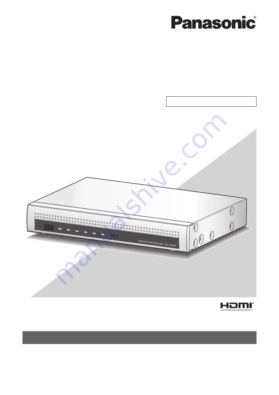
background image

Before attempting to connect or operate this product,

please read these instructions carefully and save this manual for future use.

The model number is abbreviated in some descriptions in this manual.

Installation Guide

Network Disk Recorder 

Model No.

 WJ-NX100/2E

The Operating Instructions (PDF) is on the Panasonic support website  
(https://security.panasonic.com/training_support/documentation_database/).

For professional use only

Summary of Contents for WJ-NX100

Page 1: ...nual for future use The model number is abbreviated in some descriptions in this manual Installation Guide Network Disk Recorder Model No WJ NX100 2E The Operating Instructions PDF is on the Panasonic support website https security panasonic com training_support documentation_database For professional use only ...

Page 2: ...unting 14 3 Connections 15 Connection of cameras a mouse and a PC 15 Connection of monitors 16 How to use the terminals of the ALARM CONTROL 17 ALARM CONTROL terminal on the rear side 17 Connection example for emergency recording 17 Time and polarities of the ALARM CONTROL connector 20 Connection of the AC power adapter 21 4 Turn on the devices 22 Turn on the power of the recorder 22 When turn off...

Page 3: ...rding events REC event Advanced setup Configure the settings relating to monitors Monitor Configure the settings relating to network Network Configure the settings relating to the user management User management Configure the settings relating to maintenance Maintenance Manage the hard disk drives HDD management Configure the settings relating to the extra functions Extra function Lists of the set...

Page 4: ...about the dedicated software option that receives and displays the event and error information compatible cameras and their versions Refer to the Panasonic support website https security panasonic com training_support support for latest information about the compatible cameras and functions to be added or changed by firmware upgrade The external appearance in the document may differ from the actua...

Page 5: ... subject to having strong vibration or impact Locations near magnetic field sources such as a television or speakers Locations near the devices that emit large sound and generate vibration by sound pressure Locations where condensation forms easily where temperature changes greatly or where humidity level is high Locations subject to steam and oil smoke such as a kitchen Locations which are not le...

Page 6: ...e source Grounding Confirm that the wire is connected from the SIGNAL GND terminal to earth ground A grounding connection must be made before connecting the power plug or this product to the main power supply When disconnecting the grounding wire make sure that the power plug of this product is disconnected from the main power supply For BNC cable connection Use only the recommended plug below whe...

Page 7: ... changed using the mouse wheel When no operation is made for 10 seconds or more the mouse cursor will be hidden The mouse cursor will be dis played again when the mouse is moved This section explains operation of a mouse and the soft keyboard and setting screen only The recorder can be operated using the mouse included connected to the mouse connection port either on the front or the rear side of ...

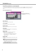
Page 8: ...field A a button This button changes the characters to be entered between capital letters and small letters Next button Changes the keys to be displayed for character entry The displayed keys are changed as follows Keys for the language selected by the language selec tion pull down menu Combination characters Special characters Enter button Determines the entered characters and closes the on scree...

Page 9: ...setup pages Easy Start button It is possible to configure the minimum settings required to operate the recorder such as date time and cam era registration Basic setup Setup page buttons Each Basic setup page will be displayed Advanced setup button The buttons to open the corresponding setup pages of the Advanced setup menu will be displayed When clicking this button again the buttons will be hidde...

Page 10: ... and monitor to this product Turn on the power to launch in the following order Turn on the power of the camera and the monitor Turn on the power of the recorder Register the Registration Key of the recorder If necessary register the Registration Key for each Additional kit Important Be sure to register the Registration Key of the recorder If the Registration key of the recorder is not registered ...

Page 11: ...Register the date time and cameras on Easy Start When it is not necessary to change other default settings it is possible to start operations If necessary perform the detailed settings for each function When the camera image is displayed on the main monitor or the web browser on the PC and can be recorded or played the recorder is ready for operation Operations flow continued ...

Page 12: ... Secure Communication Kit option To use the business intelligence function get the Registration Key of the additional business intelligence license according to the additional business intelligence kit option Each additional kit is the Activation Key Card with the Registration ID Activation Key No for the applicable additional license Note A PC or a smartphone accessible to the Internet is necessa...

Page 13: ...hion rubber large STEP3 Paste two cushion rubbers small onto the right side of the recorder at the positions shown in the following figure Cushion rubber small Approx 2 cm 13 16 inches Approx 9 cm 3 9 16 inches Cushion rubber small STEP4 Attach the rack mount bracket WV Q202 optional to the rear side of the recorder Secure them using two rack mount bracket mounting screws provided with WV Q202 Tig...

Page 14: ...en installing the recorder on a wall the height should be no more than 2 m 6 6 ft Make sure that the minimum pullout strength of the mounting screws is 196 N 20 kgf 44 lbf per screw Select the type of screws according to the material of the wall Do not use wood screws or nails Adequately reinforce the wall when mounting on a wall that is not strong enough like a wall made of gypsum boards The oper...

Page 15: ...5e or above straight PoE hub Mouse included Network Camera 4 max IP address 192 168 0 x 0 1 250 255 Except the camera s IP address Subnet mask 255 255 255 0 Default gateway 192 168 0 1 IP address 192 168 0 250 Subnet mask 255 255 255 0 Default gateway 192 168 0 1 IP address example 192 168 0 101 192 168 0 104 Subnet mask 255 255 255 0 Note Be sure to connect the cameras to the recorder with a wire...

Page 16: ...put video terminal with a BNC cable locally procured Recorder BNC cable locally procured Sub monitor BNC Main monitor HDMI HDMI cable locally procured Note Use a High Speed HDMI Cable Also when the main monitor is used in 4K 30P use a 10 2 Gbps compatible HDMI cable To maintain the stable performance without deteriorating the image quality use an HDMI cable which is 5 m or shorter Audio will be ou...

Page 17: ...output 24 V DC max 200 mA max 2 Alarm input 1 Non voltage make contact input 3 3 V pull up Approx 23 kΩ 3 Alarm input 2 Event action will be performed according to the settings 4 Emergency recording input Starting emergency recording signal input G Signal ground 5 Alarm output Alarm signal will be supplied at an event occurrence Open collector output 24 V DC max 200 mA max 6 Camera error output Si...

Page 18: ...anguage on the setup menu is set to Slave When a signal output from the other device is supplied to the time adjustment I O terminal pin no 1 and the time difference between the recorder and the other device is 29 minutes or less the clock of the recorder will be set to the time set for the other device When a signal output is supplied to the recorder 29 minutes before after the hour the clock of ...

Page 19: ...or output Recording error output Signal ground G 7 3 Connections continued Alarm connection example When a signal output from the other device is supplied to the Alarm input 1 terminal pin no 2 or Alarm input 2 terminal pin no 3 recording or an alarm action will be performed in accordance with the settings When an alarm device such as a buzzer a lamp etc is installed outside connect them to the Al...

Page 20: ...sed or the camera reset L active Face matching output At an error occurrence until the period selected for Error output duration has passed L active Alarm output The set time on the setup menu L active Time adjustment I O Input 100 ms or more Output The set time on the setup menu Input Output L active The error output duration is configured on the Advanced setup menu the Maintenance page System ma...

Page 21: ...plug from disconnection DC jack DC plug DC cable AC power adapter included Power cord included Power plug How to prevent the DC plug from disconnection Secure the DC cable at 5 cm 2 inches to 10 cm 4 inches from the DC plug with the included cable clamp through the clamp mount 5 cm 2 inches 10 cm 4 inches Clamp mount Cable clamp included Slit on the right side Pass the cable clamp included through...

Page 22: ...he recorder during startup Step 2 The administration registration window is displayed on the main monitor Enter an administrator a password and a password confirmation following the instruction on the display and click Registration Clicking OK on the displayed confirmation screen completes the administration registration Important Change the password periodically Precautions on storing the adminis...

Page 23: ...gistration Key will not be displayed from the next time When turn off the power of the recorder Follow the procedure below to turn off the power Step 1 During recording set Recording mode on Advanced setup tab under REC event under Basic Setup from Setup menu to Off to stop all recordings Operating Instructions PDF Step 2 Unplug the power plug from the power outlet after confirming that the REC in...

Page 24: ...he recorder must be rebooted by clicking the Restart button The licenses will not be effective until the recorder is rebooted When the Registration Key of the recorder is registered When the license of the additional camera kit or the additional business intelligence kit is added Step 1 Obtain the Registration Key for the recorder by following the instructions on the included Activation Key Card T...

Page 25: ...elligence kit To use the secure function click the Setup button of Registration of license Security under the system management screen shown in Step 4 and then enter the registration key of the secure communication license obtained in Step 1 in the Registration Key 1 32 fields under Secure communication on the Registration of license page The operations are the same as those of Step 6 and 7 Note R...

Page 26: ...egistration Order change of the registered camera numbers Recording frame rate image quality Smart coding GOP control and audio Other settings will remain default or will be conformed to the camera settings To apply 25 50 or 60 ips for the recording frame rate configure on the advanced recording setup for each camera on the Recording setup tab under REC event of Basic setup but not on Easy Start T...

Page 27: ...nge the setting to Off to give the IP addresses automatically When the Cancel button is clicked the top screen of Easy Start the menu to set the date time without applying the camera detection result will be displayed Step 4 Click the Next button The camera registration window opens Note To use the existing IP address of the connected cameras refer to Detect cameras for registration Detect cameras...

Page 28: ... the Camera page the Camera registration tab Operating Instructions PDF Refresh button Obtain the latest camera image after interchanging cameras Exit button Exits the setup menu and returns to the top screen of the setup menu Next button Proceeds to the settings for recording Step 9 Perform the settings for recording If the settings are performed on Easy Start the settings will be applied to all ...

Page 29: ...hard disk drives is available Note The referenced recording days will be calculated based on the assumption that recording is started on Monday The HDD consumption for the event recording will be excluded If a camera manufactured by other than Panasonic is used the value of Referenced recording days will not be displayed When configured to perform recording in high resolution and high quality reco...

Page 30: ... may not be authorized to display the images from cameras Check the user level settings of these users Operating Instructions Part of the displayed image is missing This phenomenon is caused by dispersion of display area on the monitor This is not a malfunction When a function to automatically enlarge the images in the connected monitor is enabled some part of the images may not be displayed depen...

Page 31: ...ction so as to keep the correct current time HDD indicator lights blinks red The hard disk drive is faulty Contact your dealer The error indicator blinks red A system error occurred Contact your dealer Authentication error of the camera is displayed With a new detection with Easy Start Authentication error will be displayed since the registered user name and password of the camera will be cleared ...

Page 32: ...ith a chemical symbol In this case it complies with the requirement set by the Directive for the chemical involved Disposal may be regulated in your community due to environmental considerations For disposal or recycling information please visit Panasonic website https www panasonic com us corporate sustainability html or call 1 888 769 0149 Confirmation of Compliance with UK Standards This produc...

Reviews: