background image

112

ENCODER

Setting Page

Item

Default setting

NETWORK

IP ADDRESS

192.168.0.10

SUBNET MASK

255.255.255.0

DEFAULT GATEWAY

192.168.0.1

DNS SERVER

0.0.0.0

SPEED/DUPLEX

AUTO

SYSTEM

MODE

WEB MODE

VIDEO&AUDIO ENCRYPTION

OFF

ENCRYPTION KEY (4 digits: 0 - 9)

0000

NTP

OFF

NTP SERVER HOST/IP ADDRESS

-

INTERVAL

24

TIME ZONE

(GMT-05:00) Eastern Standard Time

DAYLIGHT SAVINGS

ON

DATE [YYYY/MM/DD]

2003/01/01

DATE [hh:mm:ss]

00:00:00

DEVICE NAME

WJ-GXE900

LOCATION

-

CONTACT

-

SNMP COMMUNITY

public

START UP COMMAND*

MULTICAST

DESTINATION IP ADDRESS*

239.192.255.1

MULTICAST IP ADDRESS FOR SETUP*

239.192.255.2

MULTICAST PORT*

51203

CH1

CH2

CH3

CH4

VIDEO

CAMERA No.

1

2

3

4

CAMERA TITLE

1

2

3

4

(WITHIN 16 CHARACTERS)
DESTINATION IP ADDRESS

239.192.0.1

239.192.0.2

239.192.0.3

239.192.0.4

DESTINATION PORT No.

50000

50000

50000

50000

SOURCE PORT No.

51000

51000

51000

51000

BIT RATE

6.14 Mbps

6.14 Mbps

6.14 Mbps

6.14 Mbps

(150 ms)

(150 ms)

(150 ms)

(150 ms)

TOS BIT

0

0

0

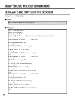
0

TTL

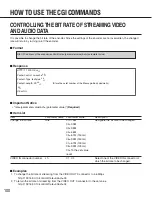
16

16

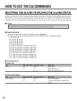
16

16

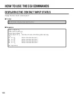
ENCODER START UP SETUP

START

START

START

START

CAMERA CABLE COMPENSATION S

S

S

S

DY

N

A

M

IC RANGE NORMAL NORMAL NORMAL NORMAL

WATERMARK

OFF

OFF

OFF

OFF

GOP

15

15

15

15

*: Valid only when "MAIN CPU MODE (MAIN CPU EXISTS)" is selected for "MODE" on the SYSTEM page of the

encoder.

DEFAULT SETTINGS

Summary of Contents for WJGXD900 - MPEG2 DECODER

Page 1: ...use MPEG2 Encoder Model No WJ GXE900 MPEG2 Decoder Model No WJ GXD900 Operating Instructions LINK1 OPERATE 100 1000 ACT STATUS 1 2 3 4 5 6 7 8 MPEG2 Decoder WJ GXD900 900 LINK1 100 1000 ACT STATUS 1 2 3 4 5 6 7 8 MPEG2 Decoder WJ GXD900 900 OPERATE STATUS 1 2 3 4 5 6 7 8 OPERATE WJ GXE900 WJ GXD900 MPEG2 Encoder WJ GXE900 900 ...

Page 2: ...nit whenever the power cord is inserted into the power source however the unit is operational only when the ON OFF switch is in the ON position Unplug the power cord to disconnect the main power for all unit CAUTION TO REDUCE THE RISK OF ELECTRIC SHOCK DO NOT REMOVE COVER OR BACK NO USER SERVICEABLE PARTS INSIDE REFER SERVICING TO QUALIFIED SERVICE PERSONNEL CAUTION RISK OF ELECTRIC SHOCK DO NOT O...

Page 3: ...your outlet consult an electrician for replacement of the obsolete outlet 10 Protect the power cord from being walked on or pinched particularly at plugs convenience receptacles and the points where they exit from the apparatus 11 Only use attachments accessories specified by the manufacturer 12 Use only with the cart stand tripod bracket or table specified by the manufacturer or sold with the app...

Page 4: ...ONS 27 Rack Mounting 28 Installing in a container box Only for the Encoder 30 Description Labels 31 SETUP 32 How to Display the Setting Menu 32 Setup with the Provided Panasonic IP Setup Software 33 Network Setup of the PC 35 SETTINGS MENUS OF THE ENCODER 41 CONTROL STATE page 43 VIDEO page 44 AUDIO page 46 ALARM page 47 RS 485 DATA PORT page 54 NETWORK page 56 SYSTEM page 57 USER page 59 HOST pag...

Page 5: ...F THE ENCODER 96 DISPLAYING THE STATUS OF THE DECODER 98 CONTROLLING THE BIT RATE OF STREAMING VIDEO AND AUDIO DATA 100 RESETTING THE ALARM DISPLAYING THE ALARM STATUS 102 DISPLAYING THE CONTACT INPUT STATUS 104 DISPLAYING THE STATUS OF VIDEO LOSS 105 MUTING THE AUDIO 106 MULTISCREEN DISPLAY 107 CONTROLLING THE CONTACT OUTPUT 108 RESTARTING THE ENCODER DECODER 110 UPDATING 111 DEFAULT SETTINGS 112...

Page 6: ...s can be connected to the MPEG2 encoder It is possible to operate cameras such as panning tilting zooming and focusing remotely The MPEG2 encoder loops through an analog video signal connected to the VIDEO IN connectors to the VIDEO OUT connectors It is possible to record images by connecting recording devices such as a digital disk recorder optional cable WV CA64 is required It is possible to dis...

Page 7: ...ed by the warranty even if it needs to be done within the warranty period Consult your dealer for servicing Cleaning Turn the power off when cleaning the unit Otherwise it may cause injuries Do not use strong or abrasive detergents when cleaning the appliance body Use a dry cloth to clean the appliance when it is dirty When the dirt is hard to remove use a mild detergent and wipe gently Network wi...

Page 8: ...owse the operating instructions pdf file on the CD ROM Browser Internet Explorer 5 5 5 5SP2 6 0 6 0SP1 Acrobat Reader Required to browse the operating instructions on the CD ROM If Acrobat Reader is not installed on the PC download the latest version of Acrobat Reader from the Adobe Systems Incorporated web site and install it LIMITATION OF LIABILITY IN NO EVENT SHALL MATSUSHITA ELECTRIC INDUSTRIA...

Page 9: ...prohibited DOCUMENT CONVENTION These operating instructions use the following convention when describing the uses and operations Encoder MPEG2 encoder Decoder MPEG2 decoder MPEG2 Image Delivery System Generic name of the MPEG2 encoder and the MPEG2 decoder CAUTIONSABOUT THE NETWORK ENVIRONMENT This unit sends a multicast stream 9 2 Mbps max x 4 streams Obtain confirmation from the network administ...

Page 10: ... no video signal will blink STATUS 5 RUN This indicator lights up when the encoder is operable OPERATE STATUS MPEG2 Encoder WJ GXE900 1 2 3 4 5 6 7 8 OPERATE STATUS SW1 ON A B C SW2 RESET WJ GXE900 1 2 3 4 5 6 7 8 BLINKING TEMPERATURE WARNING BLINKING TEMPERATURE WARNING q w e r t STATUS 6 LINK2 This indicator lights up when the initialization of the software has been completed correctly and the e...

Page 11: ...is selected DHCP will be available DIP5 Normally select OFF To change to the Main CPU mode select ON Note The Main CPU mode is the advanced function for integrated control Use these switches with the default settings for normal use DIP6 Reserved DIP7 When ON is selected the HTTP server will stop its service DIP8 Normally select OFF To select the IPL Initial Program Loader mode for start up set thi...

Page 12: ...f the encoder Do not block the ventilation openings Note The cooling fan is perishable It will need to be replaced it after around 30 000 hours of operation Replacement costs of the cooling fan are not covered by the warranty even if it needs to be done within the warranty period Consult your dealer for servicing u POWER Switch Press this switch to turn the power on or off When the power is on the...

Page 13: ...ights up during the 100BASE TX connection 1000 Indicator This indicator lights up during the 1000BASE T connection ACT Indicator This indicator lights up when the decoder is receiving or sending packets e Status Indicators STATUS 1 4 STATUS 1 4 These indicators display the status of VIDEO OUT 1 4 Each of the STATUS 1 4 indicators displays the status of the VIDEO OUT 1 4 connectors respectively The...

Page 14: ...t to ON the selected actions will be performed each time you turn the power of the decoder on DIP1 Normally select OFF When ON is selected the firmware as the start up program loaded at the factory starts up The value of the settings will not be deleted DIP2 When ON is selected the IP address and all the current settings will return to the default settings DIP3 When ON is selected the initializati...

Page 15: ... OUT 1 4 Up to 4 video display devices such as monitors can be connected Perform the settings on the settings page or use the CGI commands to select the display method QUAD Connect a video display device such as a monitor 4 images VIDEO OUT 1 4 can be displayed simultaneously in a monitor t Cooling Fan There is a built in cooling fan inside of the decoder Do not block the ventilation openings Note...

Page 16: ...monitors Send the CGI command to the decoder and set the receiving IP addresses of the camera whose pictures are to be displayed on the monitors Refer to SWITCHING STREAMING VIDEO section of HOW TO USE THE CGI COMMANDS on page 90 CONNECTIONS OPERATE STATUS MPEG2 Encoder WJ GXE900 1 2 3 4 5 6 7 8 OPERATE STATUS MPEG2 Encoder WJ GXE900 1 2 3 4 5 6 7 8 OPERATE 1 ACT 1000 100 LINK1 STATUS 2 3 4 5 6 7 ...

Page 17: ...TWORK page page 56 VIDEO page page 44 Decoder NETWORK page page 73 VIDEO page page 69 It may be required to change the network settings of a PC to switch streaming video OPERATE STATUS MPEG2 Encoder WJ GXE900 1 2 3 4 5 6 7 8 OPERATE 1 ACT 1000 100 LINK1 STATUS 2 3 4 5 6 7 8 MPEG3 Decoder WJ GXD900 OPERATE 1 ACT 1000 100 LINK1 STATUS 2 3 4 5 6 7 8 MPEG3 Decoder WJ GXD900 OPERATE 1 ACT 1000 100 LINK...

Page 18: ...d up VIDEO IN VIDEO IN MPEG2 Encoder 1 MPEG2 Decoder MPEG2 Encoder 2 100BASE TX 100BASE TX 1000BASE T 100BASE TX 10BASE T 100BASE TX Switching hub 100Mbps 1000Mbps compatible VIDEO OUT Monitor 1 Monitor 2 Monitor 3 Monitor 4 4 3 1 2 3 4 2 1 4 3 2 1 Camera 1 DESTINATION IP ADDRESS 239 192 0 1 Camera 2 DESTINATION IP ADDRESS 239 192 0 2 Camera 3 DESTINATION IP ADDRESS 239 192 0 3 Camera 4 DESTINATIO...

Page 19: ...To display the picture of the camera 5 on the monitor 1 Controlling camera camctrl cgi Definition to control the camera CHSEL x Designate the number of the VIDEO IN connector channel to which the camera to be controlled is connected Enter a number from 1 to 4 in the x part Refer to page 86 Enter after CHSEL x and enter the camera control command following to entered Example Controlling the camera ...

Page 20: ...00 1 2 3 4 5 6 7 8 OPERATE STATUS MPEG2 Encoder WJ GXE900 1 2 3 4 5 6 7 8 PC Video Input Multiscreen output VIDEO IN Video output D Sub MPEG2 Encoder MPEG2 Encoder MPEG2 Encoder MPEG2 Encoder MPEG2 Decoder PS Data 100BASE TX 1000BASE T 10BASE T 100BASE TX Router IGMP V2 100Mbps 1000Mbps compatible VIDEO OUT Monitor 1 Monitor 2 Monitor 3 Monitor 4 1 2 1 2 3 4 3 4 1 2 3 4 1 2 3 4 4 1 2 3 Digital Dis...

Page 21: ...The parameters of BAUD RATE DATA STOP BIT and PARITY should be the same values as the set parameters of the digital disk recorder Operation Example Recording streaming video To control the digital disk recorder from a PC perform the settings of DESTINATION IP ADDRESS and DESTINATION PORT No as shown below The controlling command is sent in the form of a UDP packet Refer to Receiving and Sending Se...

Page 22: ...ible Monitor 1 Monitor 2 Monitor 3 Monitor 4 1 2 1 2 3 4 3 4 Data transmission and reception will be one to one by entering same IP address to RECEIVING IP ADDRESS on the setting page of the encoder and to DESTINATION IP ADDRESS on the setting page of the decoder Settings for the MPEG2 Encoder IP ADDRESS 192 168 0 20 SOURCE PORT No 51000 Same for all Camera Input CH DESTINATION IP ADDRESS DESTINAT...

Page 23: ... the network will be converted to serial data by deleting MAC IP and UDP and then it will be sent to an RS 485 device from the RS 485 data port of the encoder OPERATE STATUS MPEG2 Encoder WJ GXE900 1 2 3 4 5 6 7 8 RS 485 data port RS 485 data port STX ETX ABC123 In case transmitting characters ABC123 to a network Sends 8 byte data including STX and ETX to the RS 485 data port STX UDP IP MAC ETX AB...

Page 24: ...uch as in the same rack and the connection distance between them is short V G RESET Reset Switch l To the reset circuit of a microcomputer 5V V G RESET Reset switch To the reset circuit of a microcomputer Reset output of an other device Short circuit Open collector or non voltage make contact Low Active less than 0 2 V Voltage endurance more than 10 V DC Sensor Security control door TRIGGER OUT 1 ...

Page 25: ...ing the selected preset position of the camera Changing the bit rate of video and audio Sending an alarm notification command to the designated IP address with the designated port number IP address Port No Alarm notification command The format of the alarm notification command is as below The alarm notification command is sent in the form of a TCP IP protocol packet Perform the settings of destina...

Page 26: ...ding audio SIGNAL GND POWER ON OFF 3 3 1 4 2 1 4 2 VIDEO OUT AUDIO OUT MIX RESET 1000BASE T 100BASE TX V G QUAD POWER ON OFF SIGNAL AUDIO IN VIDEO OUT VIDEO IN 100BASE TX RS 485 TERM 1 GND 2 3 ON OFF 4 ALARM IN TRIGGER OUT RESET 4 3 2 1 G 4 3 2 1 GGV G Network WV CA64 Sold separately Speakers with built in amplifier etc MPEG2 encoder MPEG2 decoder Amplifier Amplifier Amplifier Amplifier continued ...

Page 27: ...overheating Clear a space of more than 5 cm from both sides the top and the rear of the appliances Keep the temperature in the rack below 45 C 113 F Install the appliances in the rack as low as possible Refer to the Rack Mounting section on page 28 for further information Heat Dissipation Refer to the following to prevent fire and malfunction of the appliances Do not block the ventilation openings...

Page 28: ...einforcing brackets not included Fix the provided tapping screws into screw holes of the rack that have never been threaded before When screwing a tapping screw into a threaded screw hole thread ridge of the screw hole may be damaged Mounting the decoder 1 Remove the four rubber feet by removing the four screws from the bottom of the decoder 2 Place the supplied rack mounting brackets on both side...

Page 29: ... fixing screws for the rack mounting brackets M3x6 x12 Fixing tapping screws for rack mounting nominal diameter 5 x4 3 Install the encoder with the rack mounting brackets in the rack by using four screws not included Cautions Do not block the ventilation opening or slots in the cover to prevent the appliance from overheating Always keep the temperature in the rack below 45 C 113 F Secure the rear ...

Page 30: ...emperature is less than 40 C 104 F If temperature and humidity are beyond the value above it may affect parts inside of the encoder and cause malfunction In case of installing the container box outdoor consider influences on temperature and humidity from seasonal change sunlight and weather According to needs fabricate sun shields cooling devices heating devices drain holes etc 3 Do not install th...

Page 31: ...l to the top rear side of the encoder shown in the illustration on the right on the container box or on the rack Code label The MAC address of the appliance is described on this label Keep this label by attaching it to the provided CD ROM case etc The MAC address is also described on the label attached inside the front panel cover Labels for Decoder Description label There are descriptions about t...

Page 32: ...to be the same as the settings of the connected network Depending on the user s environment it is necessary to change the network settings of the encoder and the decoder IP addresses subnet masks etc In this case using the Panasonic IP Setup software included on the provided CD ROM will be useful to perform the settings Refer to the operating instructions pdf file on the supplied CD ROM about the ...

Page 33: ...se it is impossible to use the Panasonic IP Setup software Items included in the software IPSETUP Panasonic IP Setup Operating Instructions pdf file 1 Double click the IPSETUP icon The Panasonic IP Setup starts up The MAC address and the IP address of the connected encoder decoder will be displayed Click the REFRESH button if they are not displayed 2 Click the MAC address IP address of the encoder...

Page 34: ...rver address 5 Click the SET button after completing the settings Important It takes around 20 seconds to complete the settings of the encoder decoder after the SET button is pressed If the power cord or the Ethernet cable is detached before the settings are completed the settings may not be performed correctly ...

Page 35: ...1 Subnet mask both the encoder and the decoder 255 255 255 0 Default gateway both the encoder and the decoder 192 168 0 1 To access the camera the IP address of the PC should be 192 168 0 XXX where XXX should be a number from 2 to 254 except 10 and 11 If the IP address of the encoder recoder is set with the Panasonic IP Setup software perform the network setting of the PC according to the network ...

Page 36: ...ears 3 Click the Configuration tab 4 Click to select the TCP IP protocol of the currently used network card 5 Click the Properties button 6 Click the IP Address tab 7 Click the Specify an IP address radio button 8 Enter the IP address and the subnet mask as follows IP Address 192 168 0 9 Subnet Mask 255 255 255 0 9 Click the OK button and the window closes 10 Restart the PC to make the IP address ...

Page 37: ...dministrators before beginning the setup Begin the setup when the PC is in the same condition as it is just after the startup The Network and Dial up Connections window appears 1 Select Network and Dial up Connections Start Settings Network and Dial up Connections 2 Click the right mouse button on the Local Area Connection icon and select Properties from the pop up menu ...

Page 38: ...w the procedures to install the TCP IP The Internet Protocol TCP IP Properties window appears 3 Click to select Internet Protocol TCP IP and then click the Properties button 4 Click the Use the following IP address radio button and enter the IP address and the subnet mask as follows IP address 192 168 0 9 Subnet mask 255 255 255 0 5 Click the OK button and the window closes ...

Page 39: ...ame condition as it is just after the startup The Control Panel window appears The Network and Internet Connections window appears 1 Select Control Panel Start Control Panel 2 Double click the Network and Internet Connections icon 3 Double click the Network Connections icon ...

Page 40: ...Network Tasks menu 5 Click to select Internet Protocol TCP IP and then click the Properties button Note If the Internet Protocol TCP IP item is not displayed refer to the operating instructions of the OS and follow the procedures to install the TCP IP 6 Click the Use the following IP address radio button and enter the IP address and the subnet mask as follows IP address 192 168 0 9 Subnet mask 255...

Page 41: ...tion dialog window will be displayed Enter a user name whose access level is 1 ADMINISTRATOR and a password and click the OK button If the entered user name and password are registered the settings page will be displayed When no user is registered yet enter the default user name admin and password blank enter nothing To register users go to the USER page When authenticated the top page will be dis...

Page 42: ... details on the ALARM VIDEO LOSS ALARM page page 52 IP address to be notified of alarms Port number to be notified of alarms RS 485 DATA PORT page page 54 RS 485 data port setup Network port setup NETWORK page page 56 IP address of the encoder Subnet mask Default gateway DNS server IP address MAC address only for confirmation Transmission speed SYSTEM page page 57 System mode Video and audio encry...

Page 43: ...VIDEO IN connectors streaming video and audio data to be sent ENCODE STATE PLAY Displayed during streaming transmission STOP Displayed while stop streaming transmission CONTROL START button Click this button to start encoding when the ENCODE STATE is STOP STOP button Click this button to stop encoding when the ENCODE STATE is PLAY UPDATE button Click this button to update the settings changed on t...

Page 44: ...entered for the RECEIVING IP ADDRESS and the RECEIVING PORT No of the decoder If they are not the same pictures cannot be displayed on monitors connected to the decoder Depending on the setting for the DESTINATION IP ADDRESS the streaming method will be either multicast or unicast 1024 to 65535 are available for the DESTINATION PORT No The default settings of the DESTINATION IP ADDRESS and the DES...

Page 45: ...to be selected for this item TTL It is necessary to set the TTL Time to Live to not to send streaming data to a network that does not want it when using multicast transmission 0 to 255 are available for the TTL The selected value is diminished one by one each time the stream data passes the switching hub or the router and stops passing the switching hub or the router when it reaches to 0 The defau...

Page 46: ...ore reliable but the quality of pictures will become lower The default setting is OFF for all channels GOP In a MPEG stream coded data is a composition of frame units This unit is called GOP Group of Picture GOP consists of 3 picture groups I picture P picture and B picture The intervals between I frames become shorter when the GOP size is smaller the intervals between I frames become longer when ...

Page 47: ... signal VIDEO LOSS ALARM Setting of the action performed when video loss occurs When the encoder detects that no video signal is supplied the encoder regards it as the video loss Video loss occurs when a camera is malfunctioning the power of the camera is off a wire is broken there is connection trouble etc ALARM NOTIFICATION IP ADDRESS ALARM NOTIFICATION PORT No Enter an IP address and a port num...

Page 48: ...n alarm occurrence to the destination set on the ALARM page using the TCP IP command Camera is controlled by a preset number Changing of the bit rate The default setting is CLOSE for all ports VIDEO INPUT CH The numbers of the VIDEO IN connectors CAMERA PRESET No 1 16 When the encoder detects an alarm from a camera with preset functions connected to the VIDEO IN connector the encoder performs the ...

Page 49: ...sed contact is opened if OPEN is selected for MAKE CONTACT Timing of an open contact is closed if CLOSE is selected for MAKE CONTACT TIMER The timer starts when the alarm is detected When the entered time for this setting has past the alarm will be reset automatically Select the time seconds from the following 1 60 a second step 90 120 150 180 240 300 3 600 60 seconds interval Notes When an alarm ...

Page 50: ...No 1 16 When the encoder detects an alarm from a camera with preset functions connected to the VIDEO IN connector the encoder performs the preset control on the camera In this case the preset function settings for the camera to be controlled should be performed in advance This setting is invalid when a camera without the preset functions is connected There is no default setting BIT RATE When the e...

Page 51: ...ing has passed the alarm will be reset automatically Select the time seconds from the following 1 60 a second step 90 120 150 180 240 300 3 600 60 seconds interval Notes When an alarm with the same alarm type and number is detected and the timer is activated the timer resumes from the set value When alarms are detected successively the encoder is controlled by each alarm The default setting is TIM...

Page 52: ...The encoder does not detect any video loss alarm No alarm notification is sent The default setting is ON for all ports VIDEO INPUT CH The numbers of the VIDEO IN connectors CAMERA PRESET No 1 16 When the encoder detects an alarm from a camera with preset functions connected to the VIDEO IN connector the encoder performs the preset control on the camera In this case the preset function settings for...

Page 53: ...COMMANDS section on page 102 TIMER The timer starts when the alarm is detected When the entered time for this setting has passed the alarm will be reset automatically Select the time seconds from the following 1 60 a second step 90 120 150 180 240 300 3 600 60 seconds interval Notes When an alarm with the same alarm type and number is detected and the timer is activated the timer resumes from the ...

Page 54: ...85 data port from the following 4 800 bps 9 600 bps 19 200 bps The default setting is 9 600 bps DATA Select 7 BIT or 8 BIT The default setting is 8 BIT STOP BIT Select 1 BIT or 2 BIT The default setting is 1 BIT PARITY Select from NONE ODD or EVEN The default setting is NONE WAITING DATA SIZE TO SEND PACKET 1 1024 byte Enter a desired data length of serial data the RS 485 data port can receive at ...

Page 55: ...REFERENCE SETUP FOLLOWINGS When selecting this enter an IP address and a port number for DESTINATION IP ADDRESS and DESTINATION PORT No respectively Serial data will be sent using the entered port number for DESTINATION PORT No to the entered IP address for DESTINATION IP ADDRESS DESTINATION IP ADDRESS When REFERENCE SETUP FOLLOWINGS is selected enter the IP address of the device on the network to...

Page 56: ...ter the subnet mask of the encoder to connect to the network When the SW4 switch on the front panel of the encoder is set to ON a subnet mask assigned by DHCP will be displayed The default setting is 255 255 255 0 DEFAULT GATEWAY Enter the default gateway to connect to the network When the SW4 switch on the front panel of the encoder is set to ON a default gateway assigned by DHCP will be displaye...

Page 57: ...MAIN CPU EXISTS The Main CPU mode is the advanced function for integrated control The default setting is WEB MODE NO MAIN CPU EXISTS VIDEO AUDIO ENCRYPTION Select ON or OFF to set whether to encrypt video and audio data or not When ON is selected video and audio data of all the 4 channels will be encrypted ENCRYPTION KEY 4 DIGITS 0 9 Enter a number up to 4 digits for the encryption key code Import...

Page 58: ...and date in the respective input boxes The valid time and date ranges are as follows YYYY MM DD 2003 01 01 2038 01 19 hh mm ss 00 00 00 23 59 59 The default settings are 2003 01 01 and 00 00 00 respectively Note If these settings are performed it is possible to be informed of the time and date of an alarm occurrence When MAIN CPU MODE MAIN CPU EXISTS is selected for MODE it is possible to select w...

Page 59: ...ted regardless of the ON or OFF setting The default setting is OFF SETUP Up to 16 users can be registered A registered user can be deleted using the DELETE pull down menu in the section at the bottom of this page USER NAME PASSWORD Enter up to 16 alphanumeric characters for the user name and the password However the colon and the semicolon cannot be used PASSWORD TWICE Enter the password again for...

Page 60: ...k of the devices allowed to access the encoder Based on the entered host IP address and subnet mask the encoder calculates the valid address range The devices in this range are allowed to access the encoder For example if 192 168 0 1 is entered for the HOST IP ADDRESS and 255 255 255 0 is entered for the SUBNET MASK the valid range will be 192 168 0 1 192 168 0 255 The HOST IP ADDRESS and the SUBN...

Page 61: ...EXCLUSIVE COMMAND IP ADDRESS Enter the IP address of the device allowed to access the encoder and to enter the exclusive command If no IP address is entered exclusive command will be accepted by the encoder from any device even the host authentication setting will be ignored DELETE IP ADDRESS Select an IP address to be deleted from the pull down menu and click the DELETE button Confirm that the IP...

Page 62: ...he encoder to be updated using the ftp command Example c ftp 192 168 0 10 3 Enter a user name with the access level 1 ADMINISTRATOR and the respective password when authentication is required 4 Enter the bin command to change to the binary mode 5 Transfer the file for update to the encoder using the put command Example put name of the file to be transferred 6 Confirm the file has been transferred ...

Page 63: ...ions AUTO PAN SEQ SORT PATROL etc set on the camera will be performed by clicking this button Depending on the camera the functions using this button differ Refer to the operating instructions of the camera for further information STOP The auto functions AUTO PAN SEQ SORT PATROL etc set on the camera will be stopped by clicking this button They will be stopped also by clicking any other button Not...

Page 64: ...der and the CAMERA MENU CONTROL page will appear on the monitor connected to the PC by clicking this button CLOSE The settings menu of the camera will disappear from the monitor and the CAMERA MENU CONTROL page will be closed by clicking this button AUX1 AUX2 To activate an external device AUX1 AUX2 connected to the camera housing or the receiver select ON To deactivate an external device AUX1 AUX...

Page 65: ...ons Move the cursor to the left or to the right using the A or B buttons SET button Validate the changed settings by clicking this button When the selected item has a submenu move to the submenu by clicking this button ESC button Return to the upper level menu from the detailed settings menu or cancel the changed settings by clicking this button RESET SPECIAL button Return the setting of the selec...

Page 66: ... dialog window will be displayed Enter a user name whose access level is 1 ADMINISTRATOR and a password and click the OK button If the entered user name and password are registered the settings page will be displayed When no user is registered yet enter the default user name admin and password blank enter nothing To register users go to the USER page When authenticated the top page will be display...

Page 67: ...ground color Date display Time display NETWORK page page 73 IP address of the decoder Subnet mask Default gateway DNS server IP address MAC address only for confirmation Transmission speed SYSTEM page page 74 System mode Video and audio decryption NTP Network Time Protocol Time and date Device information Main CPU mode setup Note The Main CPU mode is the advanced function for integrated control US...

Page 68: ...connected to the decoder It is possible to switch the received stream by clicking the START button after entering the IP address or the port number directly to the RECEIVING STREAM IP ADDRESS or RECEIVING STREAM PORT No input box respectively DECODE STATE PLAY Displayed while receiving streaming STOP Displayed when receiving stream has stopped The decoding status can be checked by the STATUS indic...

Page 69: ... No for all the channels have the same IP addresses and the port number entered for the DESTINATION IP ADDRESS and DESTINATION PORT No on the VIDEO page of the encoder After the confirmation open the CONTROL STATE page of the encoder and click the START buttons for all channels Click the START button after changing the IP addresses for RECEIVING STREAM IP ADDRESS and port numbers for RECEIVING STR...

Page 70: ...ed for the latency buffer the transmission delay becomes longer If NONE is not selected the video and audio may be disturbed when turning the power of the decoder on The default setting is NONE DECODER START UP SETUP Select START or STOP to set whether the decoder starts streaming video and audio data reception automatically or not after restarting or turning the power of the decoder on The defaul...

Page 71: ...y the time on the monitor ON The time will be displayed at either the top or the bottom of monitor according to the setting for DISPLAY POSITION OFF The time will not be displayed Set the time to be displayed in the DATE input box on the SYSTEM page The default setting is ON DISPLAY POSITION Select how to display the time from the following TYPE A The camera number and the camera title will be dis...

Page 72: ... NONE DATE DISPLAY Select TYPE A or TYPE B to display the camera number the camera title and the time on the top or the bottom of the monitor YY MM DD hh mm ss Year Month Day Hour Minute Second DD MM YY hh mm ss Date Month Year Hour Minute Second MMM DD YY hh mm ss Month 3 characters Day Year Hour Minute Second The default setting is MMM DD YY hh mm ss TIME DISPLAY Select 12 HOUR or 24 HOUR to dis...

Page 73: ...oder to connect to a network The default setting is 255 255 255 0 DEFAULT GATEWAY Enter the default gateway to connect to a network The default setting is 192 168 0 1 DNS SERVER Enter the IP address of the DNS server to connect to a network No IP address is entered as the default setting MAC ADDRESS The MAC address of the decoder will be displayed It is impossible to change this value SPEED DUPLEX...

Page 74: ... be applied MAIN CPU MODE MAIN CPU EXISTS The Main CPU mode is the advanced function for integrated control The default setting is WEB MODE NO MAIN CPU EXISTS VIDEO AUDIO DECRYPTION Select ON or OFF to set whether to receive encrypted video and audio data or not When ON is selected enter the DECRYPTION KEY When video and audio data is not encrypted by the encoder select OFF When changing this sett...

Page 75: ...selected for NTP The displayed time and date is the time and date when this page is opened Enter time and date in the respective input boxes The valid time and date ranges are as follows YYYY MM DD 2003 01 01 2038 01 19 hh mm ss 00 00 00 23 59 59 The default settings are 2003 01 01 and 00 00 00 respectively Note If these settings are performed it is possible to be informed of the time and date of ...

Page 76: ...he default setting is OFF SETUP Up to 16 users can be registered A registered user can be deleted using the DELETE pull down menu in the section at the bottom of this page USER NAME PASSWORD Enter up to 16 alphanumeric characters for the user name and the password However the colon and the semicolon cannot be used PASSWORD TWICE Enter the password again for confirmation ACCESS LEVEL Select one of ...

Page 77: ...his page No host is registered at the default setting HOST IP ADDRESS SUBNET MASK Enter the IP address and the subnet mask of the devices allowed to access the decoder Based on the entered IP address and subnet mask the decoder calculates the valid address range The devices in this range are allowed to access the decoder For example if 192 168 0 1 is entered for the HOST IP ADDRESS and 255 255 255...

Page 78: ... DECODER ADD button Click to add a host after entering the host information DELETE Select a host to be deleted from the pull down menu and click the DELETE button Confirm that the host has been deleted from the pull down menu ...

Page 79: ...tory on the PC 2 Transfer the file from the PC to the decoder Follow the procedure below to transfer using the MS DOS command 1 Start up the DOS prompt Except Windows XP Start Programs Accessories MS DOS prompt In case of Windows XP Start Programs Accessories Command prompt 2 Connect to the decoder to be updated using the ftp command Example c ftp 192 168 0 11 3 Enter a user name with the access l...

Page 80: ...switches on the front panel set correctly Set the dip switches on the front panel correctly Be sure to set unused dip switches to OFF The encoder decoder does not start up normally after turning the power on 10 13 The temperature inside the encoder decoder is beyond the specified temperature Are the ventilation openings or the cooling fan slots blocked by dust etc In this case remove dust around t...

Page 81: ...sary to set the default gateway correctly to access from different networks subnets Refer to the network administrator for the default gateway address and confirm that the settings on the NETWORK page of the decoder have been set correctly The gateway address should be assigned based on the IP address of the encoder Refer to the network administrator and perform the settings When the encoder and t...

Page 82: ...protocol and network are functioning normally Otherwise check the subnet and the default gateway and perform the address settings again Are too many packets being sent to the network beyond the network s capacity Check the traffic of the network or the amount of packets using the LAN analyzer Refer to the network administrator or the network engineer for further information Delays during streaming...

Page 83: ... are lit The encoder may be down Check the status of the encoder on the CONTROL STATE page When the status is STOP click the START button The STAUS 1 4 indicators of the encoder are not lit 43 The decoder may be down Check the status of the decoder on the CONTROL STATE page When the status is STOP click the START button The image is not displayed while the STATUS 1 4 indicators of the decoder are ...

Page 84: ... recovered automatically Depending on the status of the trouble communication might be disconnected In this case try to connect again If this happens frequently reconsider the network connections Is the setting for AUDIO INPUT of the AUDIO page of the encoder set to OFF Check the settings on the AUDIO page of the encoder The image is disturbed drop frame etc 46 Is the audio device connected to the...

Page 85: ... of the decoder Displaying the status of the encoder Displaying the status of the decoder Controlling the bit rate of streaming video and audio data Resetting the alarm Displaying the alarm status Displaying the contact input status Displaying the video loss status Muting the audio Multiscreen display Controlling the contact output Changing the system mode Time and date setting Restarting the enco...

Page 86: ...ical control of the pan tilt head TILT 10 1 To move downward 1 10 To move upward Lens ZOOM 10 1 To move to WIDE 1 10 To move to TELE It will take around 30 ms for one step increment or decrement of the FOCUS parameter to adjust focusing Auto pan control ATPAN on off To start stop auto pan Auto focus control AF on Auto focus Focus control FOCUS 10 1 NEAR 1 10 FAR It will take around 60 ms for one s...

Page 87: ...xamples 1 To move the pan tilt head connected to the VIDEO IN 1 connector upward http 192 168 0 10 cgi bin camctrl cgi CHSEL 1 PAN 0 TILT 4 2 To zoom out WIDE the camera connected to the VIDEO IN 2 connector http 192 168 0 10 cgi bin camctrl cgi CHSEL 2 ZOOM 2 3 To start auto pan of the pan tilt head connected to the VIDEO IN 3 connector http 192 168 0 10 cgi bin camctrl cgi CHSEL 3 ATPAN on 4 To ...

Page 88: ...o designate the VIDEO IN connector number to be controlled Menu display MENU on To designate the menu to be displayed off To designate the menu to be closed Move the cursor upward UP 1 Move the cursor downward DOWN 1 Move the cursor to the left LEFT 1 Move the cursor to the right RIGHT 1 Change the camera menu SET set To move to the lower level esc To move to the higher level RESET set To reset re...

Page 89: ...amera connected to the VIDEO IN 1 connector http 192 168 0 10 cgi bin camctrl cgi CHSEL 1 MENU on 2 To move the cursor on the menu of the camera connected to the VIDEO IN 2 connector downward http 192 168 0 10 cgi bin camctrl cgi CHSEL 2 DOWN 1 ...

Page 90: ... Identifier to start decoding VIDEO OUT connector number ch 01 04 To designate the VIDEO OUT connector number to be switched RECEIVING IP ADDRESS PORT No address a a a a p a decimal number from 0 255 p decimal number from 1024 65535 Insert a colon between IP address and port number IP address of the encoder enc_addr 0 0 0 0 255 255 255 255 To request the first stream to the encoder which sends the...

Page 91: ...IDEO IN 3 connector destination IP address 239 192 0 3 port number 50000 of the encoder by the VIDEO OUT 1 connector multicast transmission http 192 168 0 11 control4 decode start ch 01 address 239 192 0 3 50000 enc_addr 192 168 0 10 enc_c h 03 ...

Page 92: ...g VIDEO IN connector number ch 01 04 Select a VIDEO IN connector number which starts encoding Stop encoding Item Parameter name Parameter value Description Stop encoding encode end Identifier to stop decoding VIDEO IN connector number ch 01 04 Select a VIDEO IN connector number 01 04 which stops encoding HTTP 1 1 200 OK CR LF Cache Control no cache CR LF Content Type text plain CR LF Content Lengt...

Page 93: ...ming transmission from the VIDEO IN 1 connector start encoding http 192 168 0 10 control4 encode start ch 01 2 To stop streaming transmission from the VIDEO IN 2 connector stop encoding http 192 168 0 10 control4 encode end ch 02 ...

Page 94: ...Item List Start decoding Item Parameter name Parameter value Description Start decoding decode start Identifier to start decoding VIDEO OUT channel ch 01 04 Select a VIDEO OUT channel which starts decoding RECEIVING IP ADDRESS PORT No address a a a a p a decimal number from 0 255 p decimal number from 1024 65535 Insert a colon between IP address and port number HTTP 1 1 200 OK CR LF Cache Control ...

Page 95: ... ch 01 04 Select a VIDEO OUT connector number 01 04 which stops decoding Examples 1 To start displaying images from the VIDEO OUT 1 connector start decoding http 192 168 0 11 control4 decode start ch 01 address 239 192 0 1 50000 2 To stop displaying images from the VIDEO OUT 2 connector stop decoding http 192 168 0 11 control4 decode end ch 02 ...

Page 96: ...R LF Content Length XX CR LF Store the octet number of the Message Body decimally CR LF PLAY1 xxx xxx xxx xxx yyyyy CR LF Status of CH1 or STOP1 xxx xxx xxx xxx yyyyy CR LF CR LF PLAY2 xxx xxx xxx xxx yyyyy CR LF Status of CH2 or STOP2 xxx xxx xxx xxx yyyyy CR LF CR LF PLAY3 xxx xxx xxx xxx yyyyy CR LF Status of CH3 or STOP3 xxx xxx xxx xxx yyyyy CR LF CR LF PLAY4 xxx xxx xxx xxx yyyyy Status of C...

Page 97: ...97 Example 1 To display the status of the encoder http 192 168 0 10 control4 status get Response PLAY1 239 192 0 1 50000 PLAY2 239 192 0 2 50000 PLAY3 239 192 0 3 50000 PLAY4 239 192 0 4 50000 ...

Page 98: ..._DOWN1 xxx xxx xxx xxx yyyyy or CHANNEL_SWITCHING_DOWN1 xxx xxx xxx xxx yyyyy CRLF PLAY2 xxx xxx xxx xxx yyyyy CRLF Status of CH2 or STOP2 xxx xxx xxx xxx yyyyy CRLF or NO_STREAM_DETECT2 xxx xxx xxx xxx yyyyy or STREAM_DOWN2 xxx xxx xxx xxx yyyyy or CHANNEL_SWITCHING_DOWN2 xxx xxx xxx xxx yyyyy CRLF PLAY3 xxx xxx xxx xxx yyyyy CRLF Status of CH3 or STOP3 xxx xxx xxx xxx yyyyy CRLF or NO_STREAM_DET...

Page 99: ...ideo streaming to be received and displayed Examples To display the status of the encoder http 192 168 0 11 control4 status get 1 Response when receiving streaming data from the encoder PLAY1 239 192 0 1 50000 PLAY2 239 192 0 2 50000 PLAY3 239 192 0 3 50000 PLAY4 239 192 0 4 50000 2 Response when not receiving streaming data from the encoder STREAM_DOWN1 239 192 0 1 50000 STREAM_DOWN2 239 192 0 2 ...

Page 100: ... 1M 100ms 08 9 2M 100ms 00 To the set value reset VIDEO IN connector number ch 01 04 Select one of the VIDEO IN connector of which the bit rate to be changed Examples 1 To change the bit rate of streaming from the VIDEO OUT 3 connector to 4 6 Mbps http 192 168 0 10 control4 rate 04 ch 03 2 To return the bit rate of streaming from the VIDEO OUT 3 connector to the set value http 192 168 0 10 control...

Page 101: ...101 ...

Page 102: ...h3 Contact alarm port 3 ch4 Contact alarm port 4 ch5 Camera site alarm connected to VIDEO IN 1 ch6 Camera site alarm connected to VIDEO IN 2 ch7 Camera site alarm connected to VIDEO IN 3 ch8 Camera site alarm connected to VIDEO IN 4 ch9 Video loss alarm connected to VIDEO IN 1 ch10 Video loss alarm connected to VIDEO IN 2 ch11 Video loss alarm connected to VIDEO IN 3 ch12 Video loss alarm connecte...

Page 103: ...x CR LF Status of the contact input port 3 ALM4 xxx CR LF Status of the contact input port 4 ALM5 xxx CR LF Status of the camera site alarm connected to VIDEO IN 1 ALM6 xxx CR LF Status of the camera site alarm connected to VIDEO IN 2 ALM7 xxx CR LF Status of the camera site alarm connected to VIDEO IN 3 ALM8 xxx CR LF Status of the camera site alarm connected to VIDEO IN 4 ALM9 xxx CR LF Status o...

Page 104: ...CR LF Content Length XX CR LF Store the octet number of the Message Body decimally CR LF DI1 xxx CR LF Status of the contact input port 1 DI2 xxx CR LF Status of the contact input port 2 DI3 xxx CR LF Status of the contact input port 3 DI4 xxx CR LF Status of the contact input port 4 xxx High or Low http IP address of the encoder control4 dio status HOW TO USE THE CGI COMMANDS ...

Page 105: ...deo cable is off the status will be OFF Format Response HTTP 1 1 200 OK CR LF Cache Control no cache CR LF Content Type text plain CR LF Content Length XX CR LF Store the octet number of the Message Body decimally CR LF VI1 xxx CR LF Status of VIDEO IN 1 VI2 xxx CR LF Status of VIDEO IN 2 VI3 xxx CR LF Status of VIDEO IN 3 VI4 xxx CR LF Status of VIDEO IN 4 xxx IN or OUT http IP address of the enc...

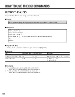
Page 106: ...ol mute on off on Stop audio output off Audio output Examples 1 To resume the muted audio output from the AUDIO OUT 1 http 192 168 0 11 control4 audio out ch 01 mute on 2 To mute audio from the AUDIO OUT 1 connector mute http 192 168 0 11 control4 audio out ch 01 mute off HTTP 1 1 200 OK CR LF Cache Control no cache CR LF Content Type text plain CR LF Content Length XX CR LF XX Display the octet n...

Page 107: ...dentifier to display multichannel VIDEO OUT channel ch 01 05 Select one of the VIDEO OUT channel numbers or select 05 to display 4 images in a multiscreen QUAD Examples 1 To display the images in a multiscreen http 192 168 0 11 control4 video out ch 05 2 To display the image from VIDEO OUT channel 1 http 192 168 0 11 control4 video out ch 01 HTTP 1 1 200 OK CR LF Cache Control no cache CR LF Conte...

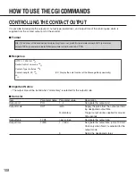
Page 108: ...output port dur ing designated output time momentary Trigger output will be supplied for around 300 seconds Output type TYPE open close Designate the output type Output time TIME 1 1 800 Designate the output time unit x 100 ms Valid only when latch is selected for the output mode 0 Retain the designated status HTTP 1 1 200 OK CR LF Cache Control no cache CR LF Content Type text plain CR LF Content...

Page 109: ... latch TYPE open TIME 150 submit ACTION 3 Trigger close output for the port 3 http 192 168 0 10 cgi bin pioctrl cgi com set_pio PIO 3 OUT momentary TYPE close submit ACTION 4 Trigger open output for the port 4 http 192 168 0 10 cgi bin pioctrl cgi com set_pio PIO 4 OUT momentary TYPE open submit ACTION 5 Open output for the port 1 and retain the current status http 192 168 0 10 cgi bin pioctrl cgi...

Page 110: ... ADMINISTRATOR and the password registered to the encoder decoder to be restarted Example Restarting the decoder http 192 168 0 11 cgi bin decoder cgi com netvup submit RESTART HTTP 1 1 200 OK CR LF Cache Control no cache CR LF Content Type text plain CR LF Content Length XX CR LF XX Display the octet number of the Message Body decimally CR LF http IP address of the decoder cgi bin decoder cgi com...

Page 111: ...word authentication will be required when trying to update the firmware of the encoder decoder Enter a user name with access level 1 ADMINISTRATOR and the password registered to the encoder decoder to be updated HTTP 1 1 200 OK CR LF Cache Control no cache CR LF Content Type text plain CR LF Content Length XX CR LF XX Display the octet number of the Message Body decimally CR LF http IP address of ...

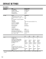
Page 112: ...DDRESS 239 192 255 1 MULTICAST IP ADDRESS FOR SETUP 239 192 255 2 MULTICAST PORT 51203 CH1 CH2 CH3 CH4 VIDEO CAMERA No 1 2 3 4 CAMERA TITLE 1 2 3 4 WITHIN 16 CHARACTERS DESTINATION IP ADDRESS 239 192 0 1 239 192 0 2 239 192 0 3 239 192 0 4 DESTINATION PORT No 50000 50000 50000 50000 SOURCE PORT No 51000 51000 51000 51000 BIT RATE 6 14 Mbps 6 14 Mbps 6 14 Mbps 6 14 Mbps 150 ms 150 ms 150 ms 150 ms ...

Page 113: ...alarm on the next page RESET TIMER SEC TIMER 10 sec TIMER 10 sec TIMER 10 sec TIMER 10 sec 2 60 90 120 150 180 240 300 3600 60SEC INTERVAL ALARM VIDEO LOSS No 1 No 2 No 3 No 4 ON OFF ON ON ON ON CAMERA PRESET No 1 64 Blank for all the camera input channels No preset control BIT RATE NO CHANGE for all the camea input channels RESET TIMER SEC TIMER 10 sec TIMER 10 sec TIMER 10 sec TIMER 10 sec 1 60 ...

Page 114: ...S The bit rate when the encoder detects an alarm both the dry contact and camera site alarm No Camera input channel Default setting 1 1 9 216 Mbps 150 ms 2 NO CHANGE 3 NO CHANGE 4 NO CHANGE 2 1 NO CHANGE 2 9 216 Mbps 150 ms 3 NO CHANGE 4 NO CHANGE 3 1 NO CHANGE 2 NO CHANGE 3 9 216 Mbps 150 ms 4 NO CHANGE 4 1 NO CHANGE 2 NO CHANGE 3 NO CHANGE 4 9 216 Mbps 150 ms ...

Page 115: ...1 CH2 CH3 CH4 VIDEO UNICAST MULTICAST MULTICAST MULTICAST MULTICAST MULTICAST RECEIVING IP ADDRESS 239 192 0 1 239 192 0 2 239 192 0 3 239 192 0 4 RECEIVING PORT No 50000 50000 50000 50000 LATENCY BUFFER NONE NONE NONE NONE DECODER START UP SETUP START START START START DISPLAY CAMERA No DISPLAY ON ON ON ON CAMERA TITLE DISPLAY ON ON ON ON DATE DISPLAY ON ON ON ON DISPLAY POSITION TYPE A TYPE A TY...

Page 116: ...ax Effective pixels 704 x 480 Frame Rate 30 fps Bit Rate 1 5 Mbps 3 0 Mbps 3 8 Mbps 4 6 Mbps 6 1 Mbps 9 2 Mbps Serial Port RS 485 four wire system RJ 11 Termination resistor ON OFF switch 4 800 bps 9 600 bps 19 200 bps Alarm Input Dry contact Terminal x4 Trigger Output Open Collector output Terminal x4 Reset Input Current loop or dry contact Terminal x1 Network Interface Network Interface 100BASE ...

Page 117: ...io Compression Method Dolby Digital Resolutions 720 x 480 pixels max Effective pixels 704 x 480 Frame Rate 30 fps Bit Rate 1 5 Mbps 3 0 Mbps 3 8 Mbps 4 6 Mbps 6 1 Mbps 9 2 Mbps Serial Port RS 232C D sub 9pin Only for maintenance Reset Input Current loop or dry contact Terminal x1 Network Interface Network Interface 100BASE TX 1000BASE T RJ 45 Compatible Network Protocols IP ICMP IGMP v2 BOOTP TCP ...

Page 118: ...118 ...

Page 119: ...nications Security Company Unit of Matsushita Electric Corporation of America Security Systems Group www panasonic com cctv Executive Office One Panasonic Way 3E 7 Secaucus New Jersey 07094 Zone Office Eastern One Panasonic Way Secaucus NJ 07094 201 348 7303 Central 1707 N Randal Road Elgin IL 60123 847 468 5205 Western 6550 Katella Ave Cypress CA 90630 714 373 7840 2003 Matsushita Electric Indust...

Reviews: