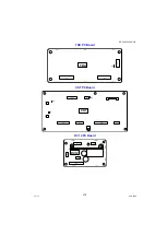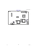
465
DP-C405/C305/C265
FEB 2008
Ver. 1.1
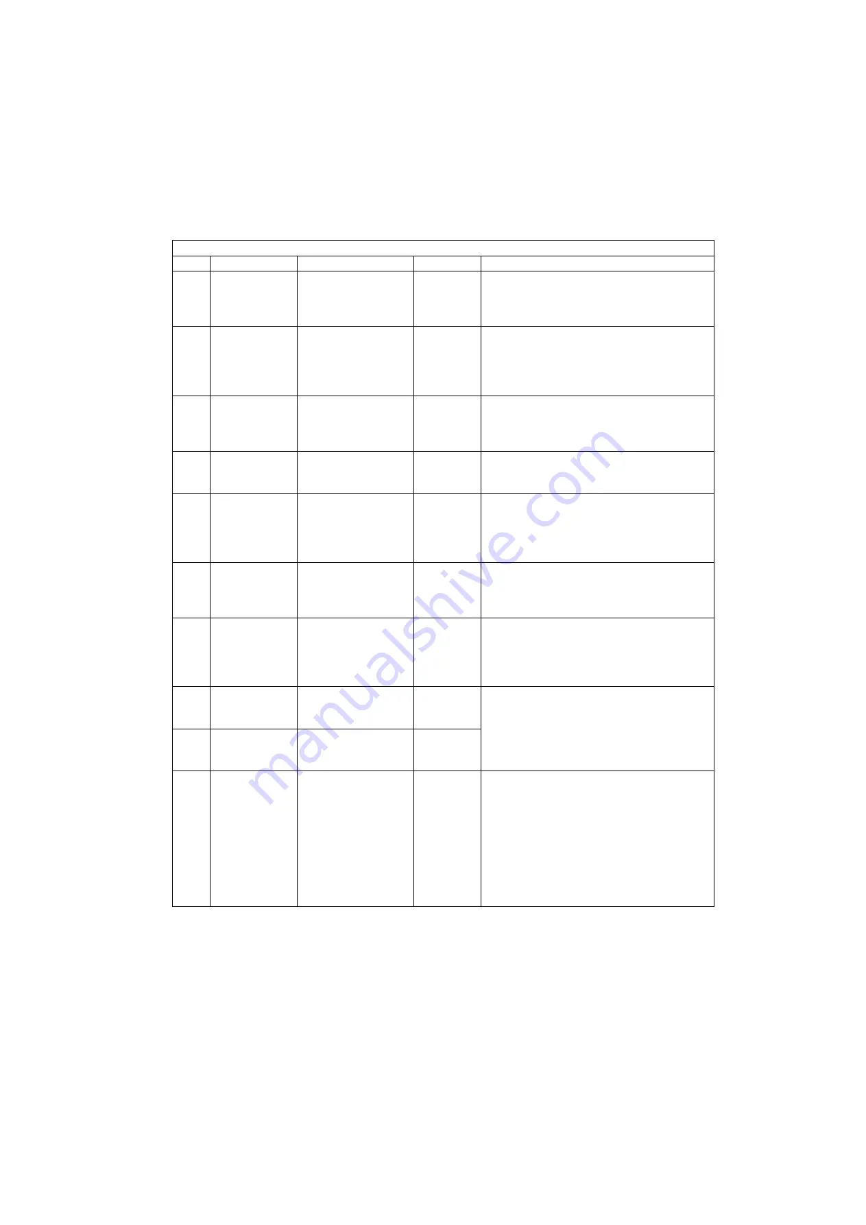
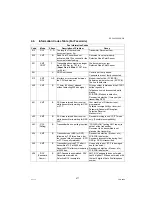
E5: System Error Codes
Code
Function
Contents
Section
Check Points
E5-01 Vp
(+24V, Printer)
Interlock Switch
failure (+24V).
Interlock
Switch
1. LVPS (+24V) Output is abnormal.
2. Check the EC PCB (+24V) connector
(CN519).
3. EC PCB is defective. (
Check F1&F14
)
E5-02 Vp
(+12V, Printer)
Interlock Switch
failure (+24V).
Interlock
Switch
1. LVPS (+24V) Output is abnormal.
2. Check the EC PCB (+24V) connector
(CN519).
3. EC PCB is defective. (IC 25 is defective)
(
Check F14
)
E5-05 Vp
(+24V, Scanner)
No LVPS (+24V) to
SCN PCB Voltage
detected.
LVPS
1. Check the SCN PCB connector (CN709).
2. SCN PCB is defective.
3. Check the LVPS connector (CN702).
4. LVPS is defective.
E5-10 Sequence Error Sequence is not
completed within a
predetermined time.
EC PCB
1. Incorrect EC ROM Version.
2. Check the EC PCB connector.
3. EC PCB is defective.
E5-11 Printer Engine
Communication
Abnormal
Communication Error
occurred between
SC, CONE, and EC
PCBs.
CONE PCB 1. Check the EC PCB connector (CN501).
2. EC PCB is defective.
3. Check the SC PCB connector (CN61).
4. SC PCB is defective.
5. CONE PCB is defective.
E5-12 Scanner Engine
Communication
Abnormal
Communication Error
occurred between
SCN and SC PCBs.
SCN/SC
PCB
1. Check the SCN PCB connector (CN709).
2. SCN PCB is defective.
3. Check the SC PCB connector (CN53).
4. SC PCB is defective.
E5-13 Printer Engine
Communication
Abnormal
During
Initialization
Communication Error
occurred between
SC, CONE and EC
PCBs.
CONE PCB 1. Check the EC PCB connector (CN501).
2. EC PCB is defective.
3. Check the SC PCB connector (CN61).
4. SC PCB is defective.
5. CONE PCB is defective.
E5-17 Scanner
Synchronization
Communication Error
occurred between
SCN and SC PCBs.
SCN/SC
PCB
1. Check the SCN PCB connector (CN709).
2. SCN PCB is defective.
3. Check the SC PCB connector (CN51).
4. SC PCB is defective.
E5-19 Scanner Line
Synchronization
Communication Error
occurred between
SCN and SC PCBs.
SCN/SC
PCB
E5-22 Finisher
Communication
Abnormal
Communication Error
occurred between
Finisher and Host
Machine.
Finisher
1. Check the EC PCB connection.
2. EC PCB is defective.
3. Check the IPC PCB connection.
4. IPC PCB is defective.
5. Check the Finisher Interface Cable
connection.
6. Check the OP LVPS connector.
7. OP LVPS is defective.
8. Check the DC PCB connection.
9. Finisher is defective.
Summary of Contents for Workio DP-C305
Page 2: ...2...
Page 3: ...3...
Page 5: ...5...
Page 6: ...6 For PB and Other Destinations not for PU USA Canada...
Page 11: ...11...
Page 12: ...12...
Page 13: ...13...
Page 14: ...14 memo...
Page 220: ...220 FEB 2008 Ver 1 1 DP C405 C305 C265 Color Test Chart 101 P N PJQRC0119Z LDR PJQRC0120Z A3...
Page 232: ...232 FEB 2008 Ver 1 1 DP C405 C305 C265 3 20 720K PM Kit DQ M35S72 DQ M32N72...
Page 400: ...400 FEB 2008 Ver 1 1 DP C405 C305 C265 LVPS CN6 LVPS CN7 Refer to SCN PC Board...
Page 401: ...401 FEB 2008 Ver 1 1 DP C405 C305 C265 LVPS CN8 Europe Specification Only...
Page 404: ...404 FEB 2008 Ver 1 1 DP C405 C305 C265 CST PCB CN603 CST PCB CN604...
Page 405: ...405 FEB 2008 Ver 1 1 DP C405 C305 C265 CST PCB CN605...
Page 406: ...406 FEB 2008 Ver 1 1 DP C405 C305 C265...
Page 407: ...407 FEB 2008 Ver 1 1 DP C405 C305 C265 CST PCB CN606...
Page 408: ...408 FEB 2008 Ver 1 1 DP C405 C305 C265...
Page 409: ...409 FEB 2008 Ver 1 1 DP C405 C305 C265 CST PCB CN607...
Page 410: ...410 FEB 2008 Ver 1 1 DP C405 C305 C265 CST PCB CN608...
Page 412: ...412 FEB 2008 Ver 1 1 DP C405 C305 C265 TRU PCB CN613...
Page 414: ...414 FEB 2008 Ver 1 1 DP C405 C305 C265 RLB PCB CN176...
Page 615: ...615 DP C405 C305 C265 FEB 2008 Ver 1 1 1 2 3 4 5 6 7 8...
Page 752: ...752 FEB 2008 Ver 1 1 DP C405 C305 C265 memo...
Page 847: ...847 DP C405 C305 C265 FEB 2008 Ver 1 1 2 Motor PCBs Fig 5 009 M1 M2 M8 M5 M4 M3 M7 M6 1...
Page 919: ......
Page 920: ...Published in Japan...


