2-1
Chapter 2 Maintenance
Chapter 4 Disassembly/Assembly and Adjustment
2. 1 Preface
This section contains procedures required for repair (Disassembly, Assembly, Replacement and
Adjustment) in the field service. Special adjustment procedures, however, are explained in
Chapter 1, Special Mode Setting, or Chapter 3, Diagnostic Mode/Program.
2. 1. 1 How to Use the Disassembly/Assembly/Adjustment Section
1.
For installation procedures, only NOTES are described here since the installation
procedures are reverse of removal ones.
2.
(Fig. X) at the beginning of a procedure indicates that its detailed steps are shown in
illustration. Numbers in the illustration indicate the sequence of the steps.
3.
(REPX.X.X) at the end of a procedure indicates the replacement procedure to be referred to.
4.
Item numbers of disassembly/assembly and adjustment procedures (i.e. REP/ADJ numbers)
correlate to PL numbers of Chapter 5 Parts List. So, an appropriate replacement or
adjustment procedure can easily be referred to from a PL number or vice versa. E.g. The
replacement or adjustment procedure of Component PL1. 1 is REP1. 1. X or ADJ1. 1. X.
5.
When replacement/adjustment procedures or title items vary by modification or model, the
modification number or the model are indicated at the beginning or the end of the respective
titles or procedures.
E.g. 1 REPX.X.X Main PWB [w/Tag 1V]
*Indicates that the entire procedure under this title applies to machines with Tag 1.
E.g. 2
6.
Positions or directions of the machine and directions inside the machine used in the
procedure are defined as listed below.
(1) Front: Front of the machine
(2) Right: Right-hand side facing the machine.
(3) Left: Left-hand side facing the machine.
(4) Rear: Rear facing the machine.
2. 1. 2 Glossary and Symbols
Terminology and symbols used throughout this manual are explained.
INSTRUCTION:
Used to alert you to a procedure which, if not strictly observed, could result in
damage to the machine or equipment.
Reference
Used to describe the technical terminology and supplementary explanations.
Purpose
Used to explain purpose of adjustment.
REP: Indicates the disassembly/assembly procedure for reference.
ADJ: Indicates the adjustment procedure for reference.
PL: Indicates the parts list for reference.
ASSY: Means Assembly.
Symbol
Description
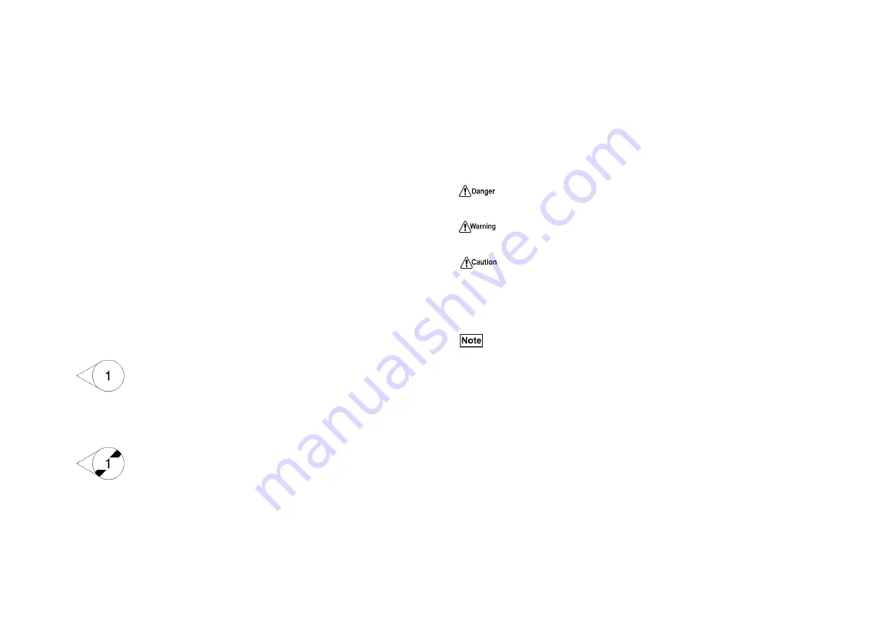
Illustration 1
Illustration 1: Indicates a specific part has been modified by the
tag number within the circle.
Illustration 2
Illustration 2: Indicates that the configuration of the part shown
is the configuration before the part was modified by the number
within the circle.
Indicates an imminently hazardous situation which, if operators do not follow the
practice, procedure, condition, or statement, will result in death or serious injury.
Indicates a potentially hazardous situation which, if operators do not follow the
practice, procedure, condition, or statement, could result in death or serious injury.
Indicates a potentially hazardous situation which, if operators do not follow the
practice, procedure, condition, or statement, may result in injury, or property-
damage-only accidents.
Used to emphasize the procedure, servicing, and regulation.
Summary of Contents for Workio DP-C401
Page 4: ...This page is intentionally left blank ...
Page 5: ...Chapter 1 General ...
Page 22: ...1 16 Chapter 1 General 1 3 Type of Paper ...
Page 23: ...1 17 Chapter 1 General ...
Page 24: ...Chapter 2 Maintenance ...
Page 63: ...Chapter 3 Troubleshooting ...
Page 118: ...3 44 Chapter 3 Troubleshooting I F PWB PL9 1 MCU PWB PL13 1 ...
Page 445: ...Chapter 4 Parts List ...
Page 548: ......


