2-16
Chapter 2 Maintenance
Check
1.
Select [
DC612
(Color Test Pattern)].
Clicking the above DC612 prints out in the following modes automatically.
Print out the following patterns.
• Pattern No. 3
• No. of Copies: 5
• Tray No: Select the tray to be checked.
• Select the color mode: K (Select Black.)
• Screen: 600 dpi
2.
Click [Execute].
3.
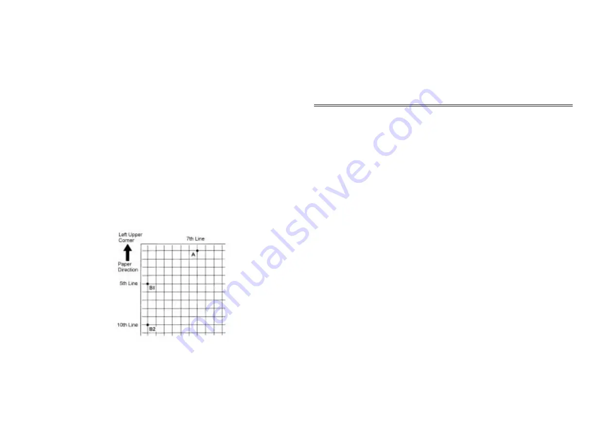
Take out the third pattern that was printed out and measure the following points. (Fig. 1)
• Lead Edge: from the edge of the paper to A in the figure (intersection between the 7th
line from the left top edge and the first line from the lead edge of the paper)
• Side Edge:
Legal or larger: from the left of the paper to B1 in the figure (intersection between
the 1st line from the left top edge and the 10th line from the lead edge of the
paper)
Letter or smaller: from the left of the paper to B2 in the figure (intersection
between the 1st line from the left top edge and the 5th line from the lead edge of
the paper)
(Fig. 1) j0mf40953
4.
Confirm that each measurement value of the lead edge and side edge are 21.6±0.5 mm
respectively.
Adjustment
Procedure
1.
Adjust in the following NVM that each measurement value of the lead edge and side edge
are 21.6±0.5 mm..
2.
After adjustment, print out the patterns in the same mode and measure them again until they
are within the specific range.
Adjustable Modes
NVM
Default
Adjustment
Range
Changes
Lead
Edge
• ALL
• Tray
• Dup (Side 2)
• MSI (Plain
Paper)
• MSI (Heavy
Weight paper 1)
• MSI (Heavy
Weight paper 2)
•
DC131
[742-028]
•
DC131
[742-030]
•
DC131
[742-038]
•
DC131
[742-032]
•
DC131
[742-033]
•
DC131
[742-034]
20
20
20
20
20
20
0~40
1 Step =
0.2544 mm
Reference
5 Step
= approx. 1 mm
Smaller values
make the margin
larger.
Side
Edge
• ALL
• MSI
• Dup (Side 2)
• 1 Tray
• 2 Tray
• 3 Tray
• 4 Tray
• Tray (2, 3, 4)
•
DC131
[742-025]
•
DC131
[742-026]
•
DC131
[742-027]
•
DC131
[742-053]
•
DC131
[742-076]
•
DC131
[742-077]
•
DC131
[742-078]
•
DC131
[742-079]
25
20
22
22
20
20
20
25
0~50
1 Step =
0.2117 mm
Reference
4 Step
= approx. 1 mm
Smaller values
make the side edge
larger. (The image
is placed to the
rear.)
Summary of Contents for Workio DP-C401
Page 4: ...This page is intentionally left blank ...
Page 5: ...Chapter 1 General ...
Page 22: ...1 16 Chapter 1 General 1 3 Type of Paper ...
Page 23: ...1 17 Chapter 1 General ...
Page 24: ...Chapter 2 Maintenance ...
Page 63: ...Chapter 3 Troubleshooting ...
Page 118: ...3 44 Chapter 3 Troubleshooting I F PWB PL9 1 MCU PWB PL13 1 ...
Page 445: ...Chapter 4 Parts List ...
Page 548: ......


